Chapter 7: counters, 1 introduction, 1 clka, clkb and ix signals – Sensoray 826 User Manual
Page 32: Counters, Introduction, Clka, clkb and ix signals, Figure 5: counter channel (1 of 6)
Chapter 7: Counters
7.1 Introduction
The model 826 board has six identical 32-bit programmable counter channels, numbered 0 to 5. Each counter channel can
implement a complete solution for a variety of common applications, including incremental encoder interface, event
counter, timer, pulse generator, PWM generator, pulse width measurement, period measurement, and frequency
measurement. See “Application Connections” for tips on connecting external signals to counter channels, and “Common
Applications” for programming strategies.
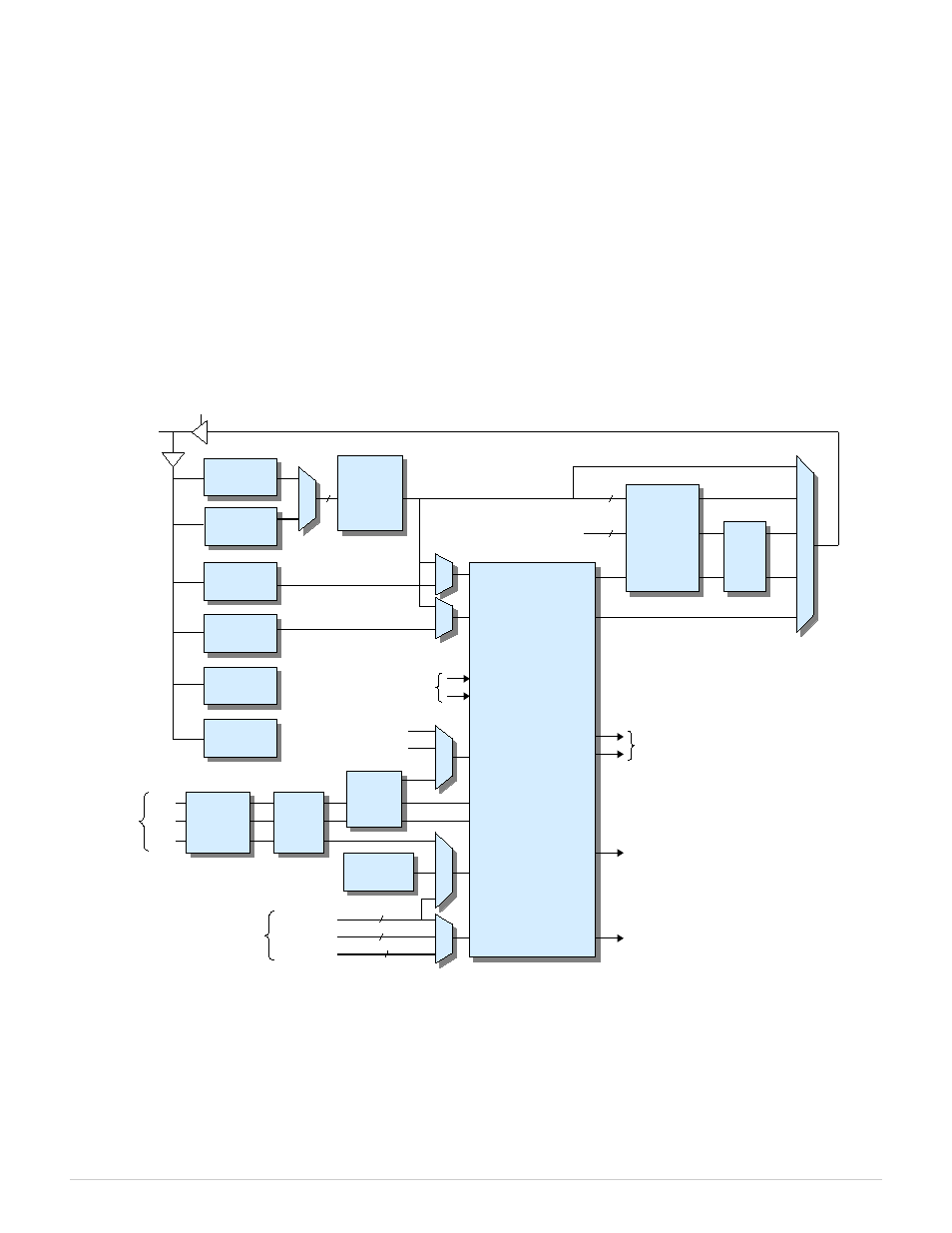
As shown in Figure 5, each channel can connect to as many as five external signals. Three input signals (ClkA, ClkB, and
IX) are accessible through dedicated header pins. Two additional signals (input ExtIn and output ExtOut) can be routed to
general-purpose digital I/O pins if physical access to these signals is needed.
Figure 5: Counter channel (1 of 6)
7.1.1 ClkA, ClkB and IX Signals
A channel can accept external signals on its ClkA and ClkB inputs consisting of either a single-phase or quadrature-
encoded clocks. The maximum count rate is 25MHz regardless of external clock type. Single-phase clocks having exactly
50 percent duty rate can be counted at up to 25MHz; the maximum count frequency must be derated for other duty rates
(see Specifications for details). Quadrature clocks up to 25 MHz (x1 multiplier), 12.5 MHz (x2), and 6.25 MHz (x4) are
supported, with suitable derating for deviations from 90 degree clock phasing.
826 Instruction Manual
27
Counters
Timestamp
50MHz
1MHz
DIO_in
From I/O
Header
ClkB
ClkA
ExtOut
IX
Cascade In
(from chan-1)
Error
Clk
6
To Routing Matrix
To Interrupt System
Cascade Out
(to chan+1)
32
48
32
32
Tick
Generator
Status
Reason
ExtIn
Index
Dir
Overflow
Overflow
Underflow
Underflow
ExtOut
IRQ
Snapshot
FIFO
Preload0
Reg
Hold
Reg
Counter
Core
Control
Logic
Clock
Decoder
Compare0
Reg
Line
Receivers
Mode
Reg
Snapshot
Config Reg
Preload1
Reg
Compare1
Reg
=
=
Internal
Data Bus
From Routing Matrix
Virtual outs
6
Noise
Filters