Chapter 8: digital i/o, 1 introduction, 1 signal routing matrix – Sensoray 826 User Manual
Page 53: Digital i/o, Introduction, Signal routing matrix
Chapter 8: Digital I/O
8.1 Introduction
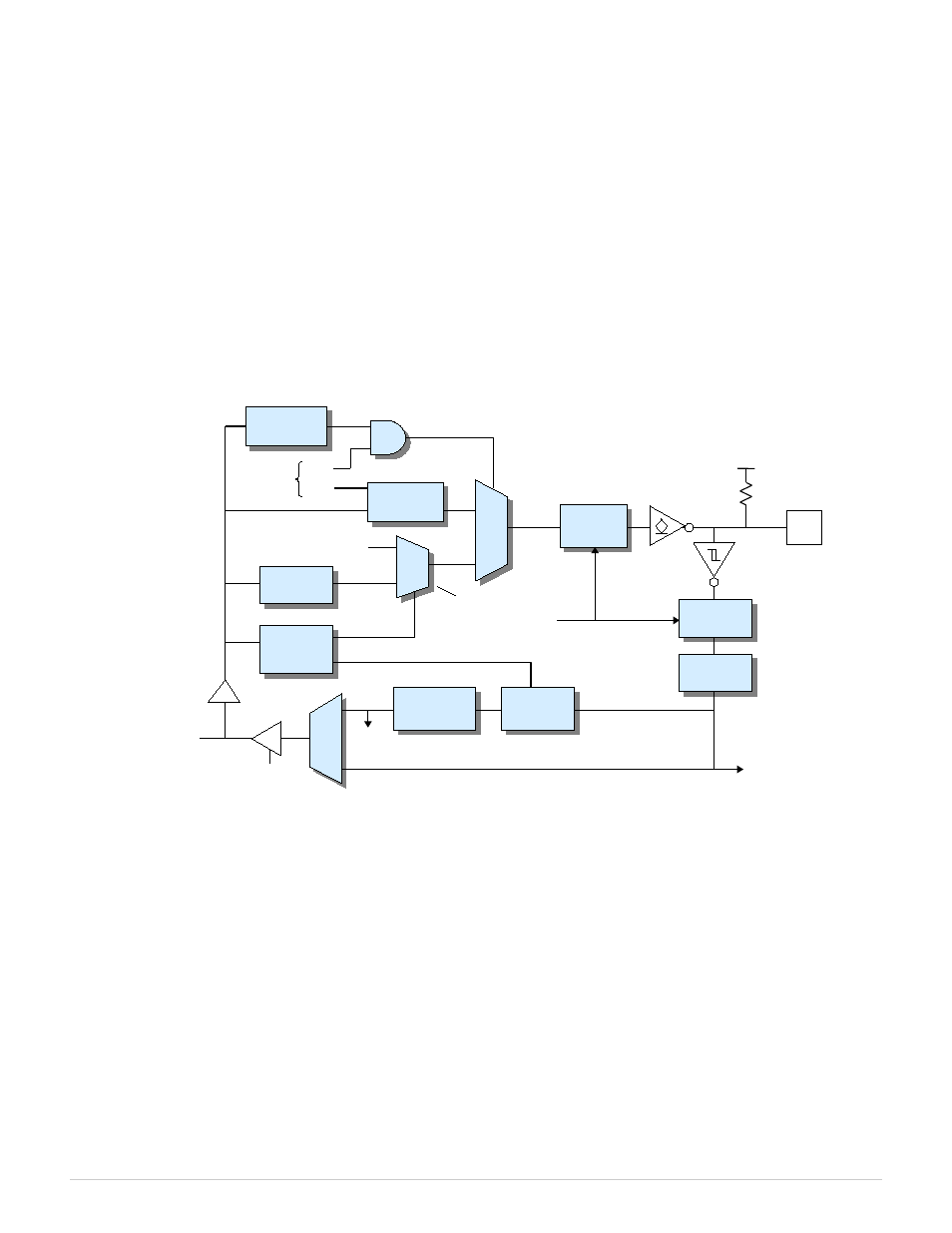
The 826 board has 48 general-purpose digital I/O (DIO) channels. On the output side, each channel has a one-bit, writable
output register, a synchronous drive register, and an inverting open-drain buffer that drives the channel's I/O pin. The open-
drain buffer enables the pin to be driven low by the channel's output buffer or by an external signal. The pin, when not
driven, is pulled up to +5V by a 10 kohm resistor. The output is high impedance when the board is unpowered so as to
prevent unintended activation of an external solid state relay, if one is connected. The pin's physical state is sampled by an
input register and then processed by a noise/debounce filter. The filter output is monitored by an edge detector and can also
be directly read by the host computer.
Figure 7: DIO channel (1 of 48)
DIO signals are active-high on the local bus and active-low on the I/O pin. Writing a '1' to the output register causes the I/O
pin to be driven low, whereas writing '0' allows the pin to be internally pulled up or driven high or low by an external
circuit. Logic '0' must be written to the output register if the pin will be driven high by an external circuit; this will prevent
high currents that could potentially damage the pin's output buffer.
The value read from a DIO channel indicates the filtered, sampled physical state of the I/O pin. If no external signals are
driving the pin then the read value will equal the value stored in the drive register. The read value will differ from the drive
register value if the drive register contains '0' while an external circuit drives the pin low.
Most of the host-accessible DIO registers support masked write operations so as to implement the atomic bit set and clear
functions required for high performance, thread-safe operation.
8.1.1 Signal Routing Matrix
Each DIO channel connects to the board's internal signal routing matrix as shown in Figure 7. The matrix can be
programmed to route the DIO connector pin to or from another interface (e.g., counter, watchdog, analog input system) so
that the pin will act as a physical input or output for that interface.
826 Instruction Manual
48
Digital I/O
Alternate Source
10K
To DIO_in Signal
Routing Matrix
IRQ
Sample Clock
+5V
DIO_out Signal Router
Safe Enable
Reg
SAF
Internal
Data Bus
Output
Reg
I/O
Pin
Capture
Reg
Config
Reg
Input
Reg
Edge
Detect
Drive
Reg
Safe
Data Reg
SWE
WE
From
Safemode
Controller
Noise
Filter