Chapter 4: virtual outputs, 1 introduction, 1 safemode – Sensoray 826 User Manual
Page 14: 2 programming, 1 s826_virtualwrite, Virtual outputs, Introduction, Safemode, Programming, S826_virtualwrite
Chapter 4: Virtual Outputs
4.1 Introduction
The board has six virtual digital output channels, numbered 0 to 5, that can be used by software to signal various interfaces
on the board. The virtual output channels are physical circuits that are architecturally similar to the board's general-purpose
digital output channels, but they cannot be routed to the board's headers or connected to external circuitry.
Each virtual output channel is connected to the board's internal signal routing matrix, which in turn routes the channel's
output signal to other on-board interfaces under program control. A virtual output channel can be routed to the ExtIn input
of one or more counter channels, or to the ADC trigger input, or to combinations of these.
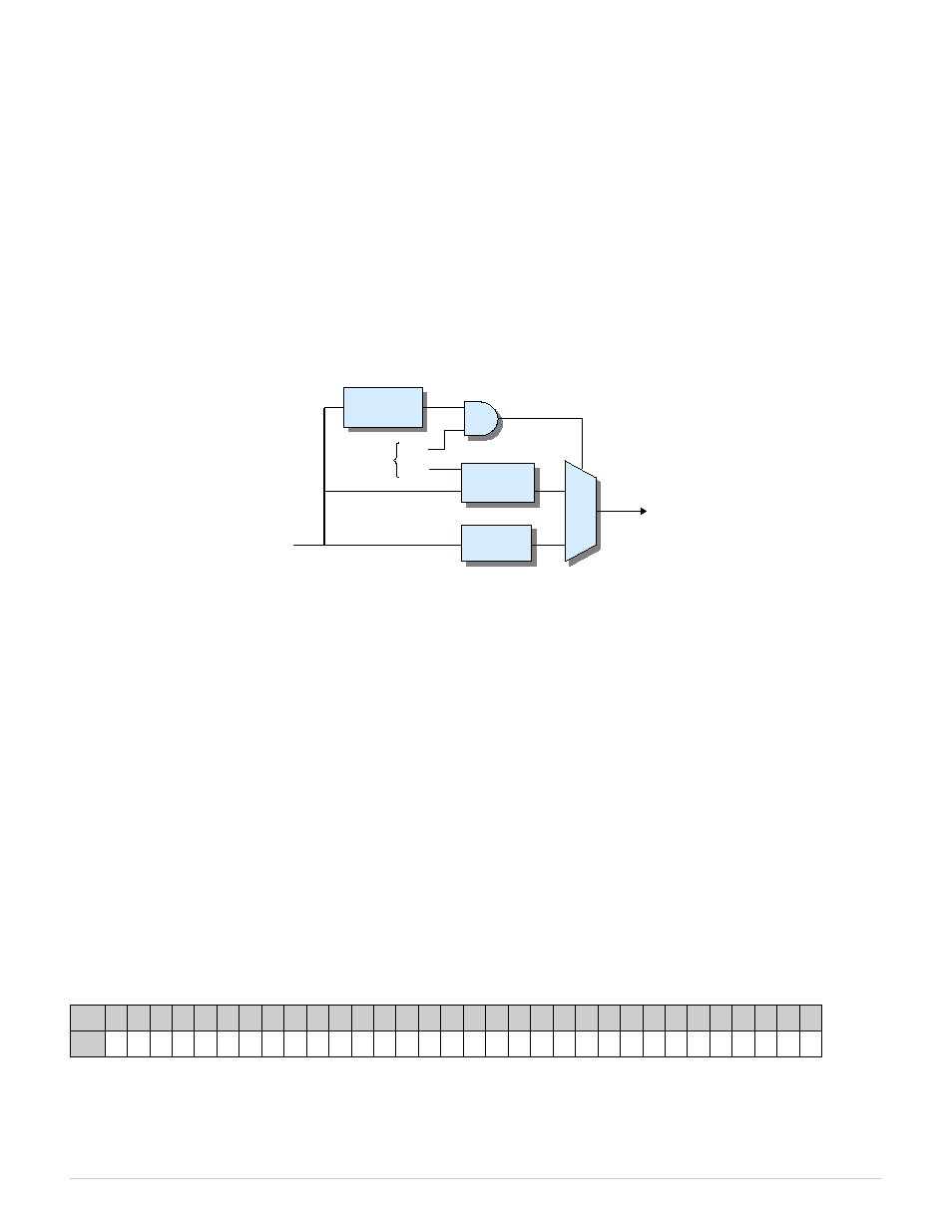
Figure 2: Virtual output channel (1 of 6)
4.1.1 Safemode
Safemode is activated when the SAF signal (see Figure 2) is asserted. When operating in safemode, the virtual output state
is determined by the Safe Enable and Safe Data registers: when Safe Enable equals '1' the pin will be driven to the fail-safe
value stored in Safe Data; when Safe Enable equals '0' the pin will output the normal runmode signal from its output
register.
Upon board reset, the Safe Enable register is set to '1' so that the virtual output will exhibit fail-safe behavior by default
(i.e., it will output the contents of the Safe Data register when SAF is asserted). Fail-safe operation can be disabled for a
virtual output channel by programming its Safe Enable register to '0'.
The Safe Data register is typically programmed once (or left at its default value) by the application when it starts, though it
may be changed at any time if required by the application. It can be written to only when the SWE bit is set to '1'. See
“Safemode Controller” for more information about safemode.
4.2 Programming
The virtual output API functions employ individual bits to convey information about the virtual output channels, wherein
each bit represents the information for one channel. The information is organized into a single quadlet as follows (e.g., “v5”
= virtual output channel 5):
Bit
31 30 29 28 27 26 25 24 23 22 21 20 19 18 17 16 15 14 13 12 11 10 9
8
7
6
5
4
3
2
1
0
DIO 0
0
0
0
0
0
0
0
0
0
0
0
0
0
0
0
0
0
0
0
0
0
0
0
0
0 v5 v4 v3 v2 v1 v0
4.2.1 S826_VirtualWrite
The S826_VirtualWrite function programs the virtual output registers.
826 Instruction Manual
9
Virtual Outputs
To Signal
Routing Matrix
Safe Enable
Reg
SAF
Output
Reg
Safe
Data Reg
SWE
WE
From
Safemode
Controller
Internal
Data Bus