Chapter 6: analog outputs, 1 introduction, 1 safemode – Sensoray 826 User Manual
Page 28: Analog outputs, Introduction, Safemode
Chapter 6: Analog Outputs
6.1 Introduction
The 826 board has eight 16-bit, single-ended digital-to-analog converter (DAC) channels. Each channel can be
independently configured to generate output voltages across one of four output voltage ranges: 0 to +5V (default upon
reset), 0 to +10V, -5 to +5V, and -10 to +10V.
Each DAC channel has a setpoint and configuration register. A channel's output voltage is programmed by writing to its
setpoint register. Before programming the setpoint, the DAC must be configured for the desired output range by writing to
its configuration register.
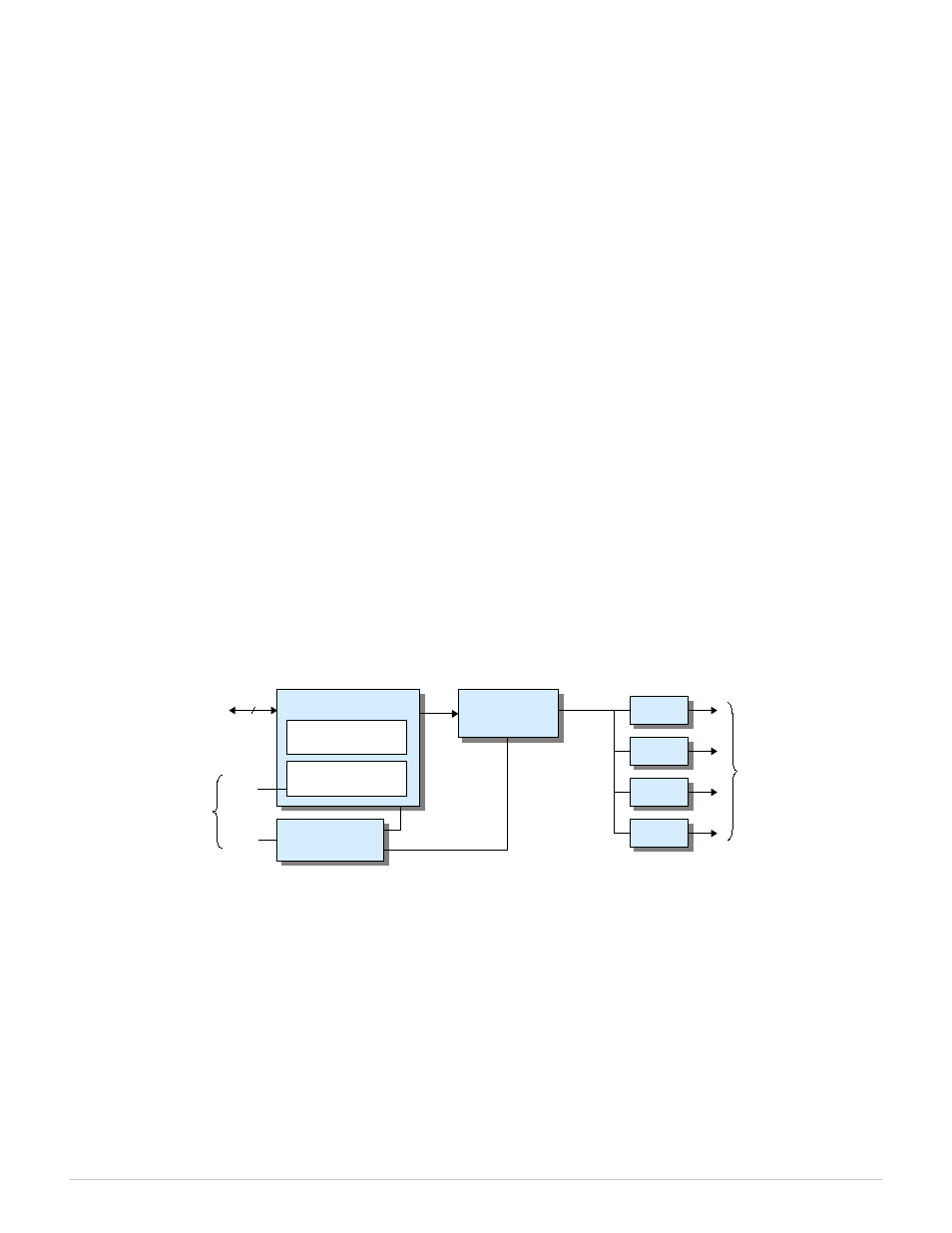
Setpoint and configuration values are serially transmitted to the DAC devices over a high speed serial bus (Figure 4). The
interface includes a dual-port RAM that allows the host to write setpoint and configuration values to the board while the
serial bus is busy. If multiple untransmitted values are pending in the RAM, the controller will employ round-robin
arbitration to ensure all pending values are transmitted in a fair and timely fashion. The data serializer requires 1.04 µs to
transmit each setpoint or configuration value.
The board has two identical DAC interfaces as shown in Figure 4. Each interface manages a group of four DAC channels.
One interface manages channels 0 to 3 and the other interface manages channels 4 to 7. The two interfaces operate
concurrently, thus making it possible to simultaneously write to two DACs that reside in different four-channel groups. For
example, DAC channels 0 and 4 can be written to simultaneously.
The host may write setpoint and configuration values to the board at any time. If a new value is written to the RAM for a
particular channel before that channel's previously written value has been transmitted, the previous RAM value will be
overwritten and only the new value will be transmitted. Consequently, the host is allowed to write setpoint data at a rate that
exceeds the serial bus bandwidth, though doing so will result in dropped samples.
Figure 4: Analog output interface (1 of 2)
6.1.1 Safemode
The dual-port RAM has two memory banks, one for normal operation (“runmode”) and another for “safemode” operation.
The runmode bank stores the setpoint and configuration values that are used during normal operation; these values may be
changed at any time as required by the application. The safemode bank contains alternate fail-safe settings that are typically
programmed once during program initialization (or left at their default settings). Setpoint and configuration values can be
written to the runmode bank at any time, but the safemode bank can only be written when SWE = '1'
The safemode signal (SAF) determines which RAM bank is being used by the interface controller ('1' = safemode, '0' =
runmode). When SAF changes state, the appropriate RAM bank is selected and all of the DAC channels are reprogrammed
to the settings stored in that bank. See “Safemode Controller” for more information about the fail-safe system.
826 Instruction Manual
23
Analog Outputs
4 Analog
Outputs
Runmode bank
Internal
Data Bus
32
Safemode bank
Dual Port RAM
Interface
Controller
Data
Serializer
DAC
DAC
DAC
DAC
SWE
SAF
WE
Serial Bus
From
Safemode
Controller