Rxt 351 dc indoor unit fault analysis – REMKO RXT xxx DC User Manual
Page 33
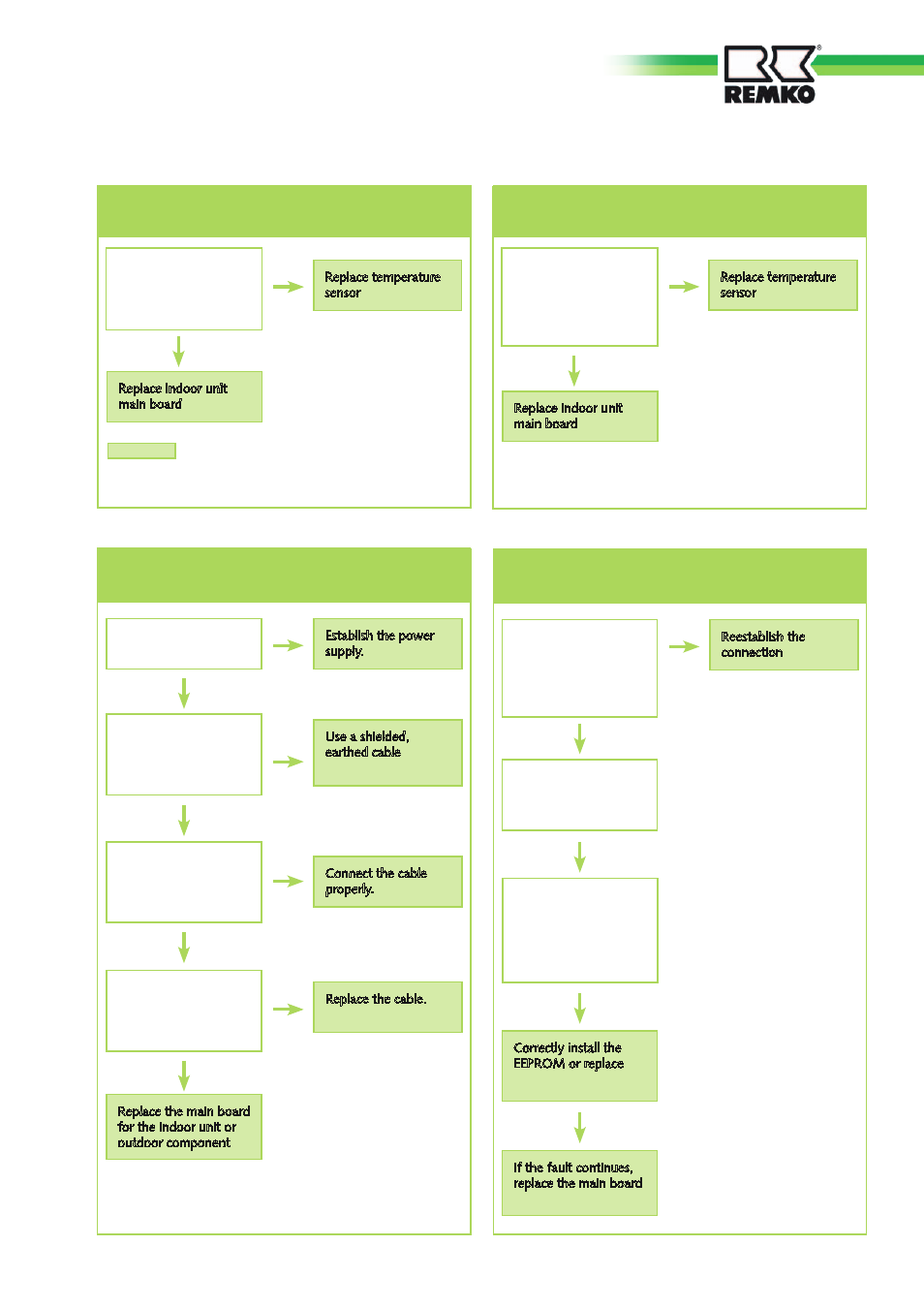
RXT 351 DC indoor unit fault analysis
No
No
Yes
Yes
No
Yes
No
Yes
Is the resistance of the
temperature sensor
OK? (white cable)
(Table 1 P92-94)?
No
Replace temperature
sensor
Replace indoor unit
main board
Yes
Note:
The room temperature sensor and vaporiser sensor
are brought together in a single connector, CN9
1. Operation light flashes at 5 Hz: fault on the
room temperature sensor
3. Timer light flashes at 5 Hz: communication
error between indoor unit and outdoor component
Establish the power
supply.
Is there voltage in the
indoor unit?
Is the connecting cable
shielded, and is it
earthed?
Use a shielded,
earthed cable
Is the cable connecting
the indoor unit and
outdoor component
properly connected?
Connect the cable
properly.
Is the cable connecting
the indoor unit and
outdoor component
damaged?
Replace the cable.
Replace the main board
for the indoor unit or
outdoor component
Is the resistance of the
temperature sensor OK?
(black cable)
(Table 1 P92-94)?
No
Replace temperature
sensor
Replace indoor unit
main board
Yes
2. Defrost light flashes at 5 Hz: fault on the
vaporiser sensor
No
Yes
Yes
Yes
4. Alarm light flashes at 5 Hz: float switch /
condensation pump defective
Reestablish the
connection
Is the connection
between the float
switch and the main
board OK?
(connector CN2)
Replace float switch.
Is fault still present?
Is the EEPROM
damaged or improperly
installed (note the
position of the
semicircular recess!)?
Correctly install the
EEPROM or replace
If the fault continues,
replace the main board
33