5 electrical circuit diagram, Remko mxd, Electrical circuit diagram – REMKO MXD 202 User Manual
Page 32
8.5
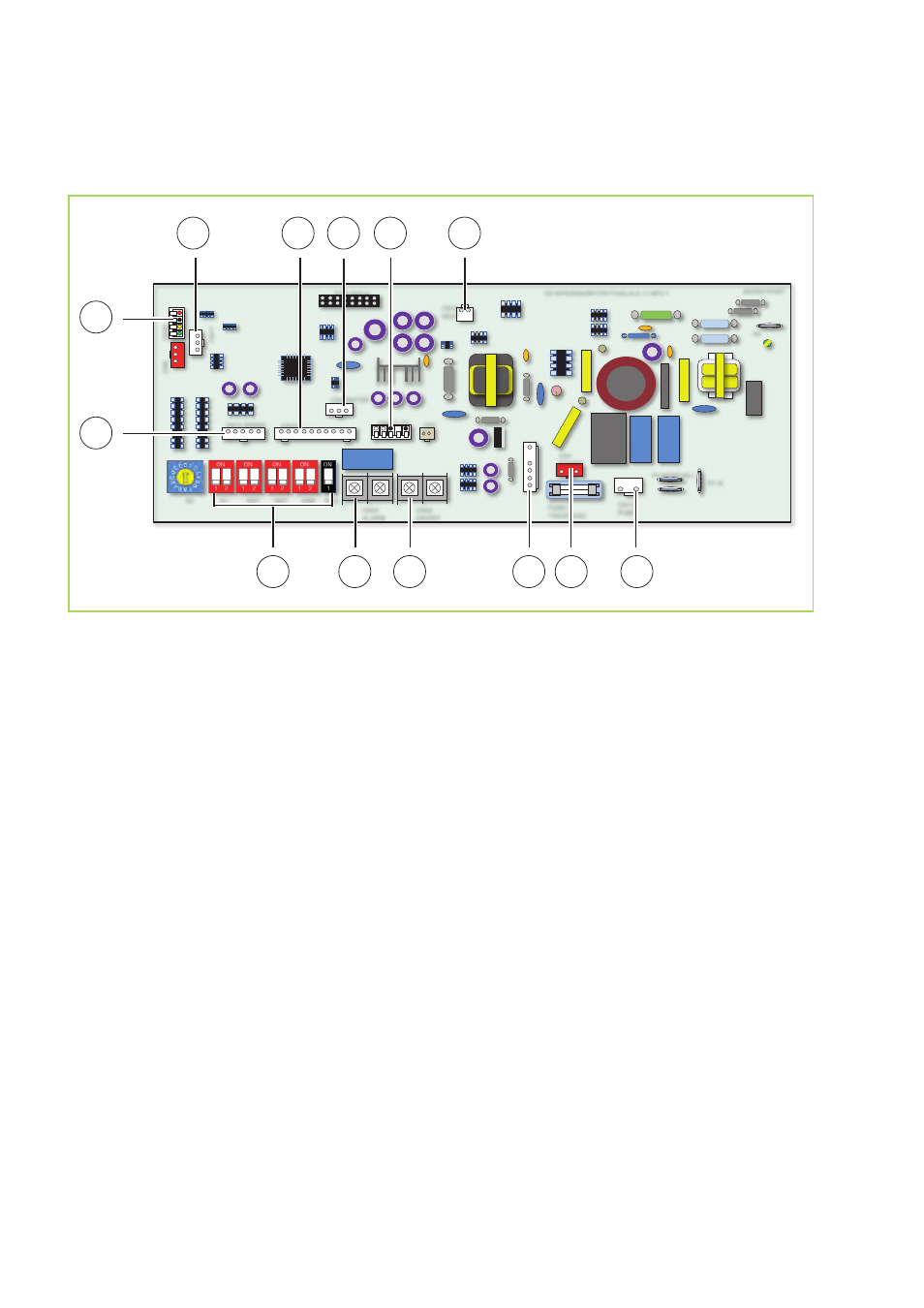
Electrical circuit diagram
MXD 202-352
CE-KFR20Q4/BP3TN1Y(hb)-A.D.11.NP2-1
202302141057
CN23
ON/OFF
CN33
ALARM
SW6
SW1
SW7
S1
S2
FUSE1
T5A/250VAC
C
N
9
C
N
40
C
N
17
CN14 SWING
CN10
CON-debug
CN5 WATER
CN6 T1 T2
CN7
CN12
HEAT
CN1
POWER
CN13
PUMP
P4 NEWFAN L
P5 NEWFAN N
P1 N
P6
CN15
2
1
4
3
5
6
7
8
9
A
10
11
SW2
12
Fig. 43: Electrical circuit diagram
A:
Power supply control board
1:
Swing motor
2:
Connectivity cable remote control
3:
MCC-bus
4:
Connection display board
5:
Liquide level switch condensate
6:
Probe suction pipe, probe room temperature
7:
External start/stop contact
8:
DIP-switch
9:
Alarm contact (optional)
10:
External start/stop contact (optional)
11:
Evaporator fan motor
12:
Connection condensate pump
REMKO MXD
32