Additional applications, Sa e-bus controller technical guide, Water source heat pump protection module – Orion System SA E-BUS Controller User Manual
Page 35
SA E-BUS Controller Technical Guide
Additional Applications
35
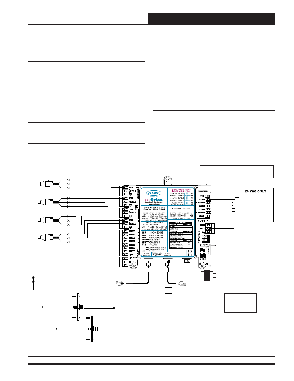
Water Source Heat Pump Protection Module Overview and Wiring
Figure 28: Water Source Heat Pump Protection Module to E-BUS Distribution Module Wiring Diagram
Water Source Heat Pump Protection
Module
The Water Source Heat Pump Protection Module (OE-334-23-WPM-
A)protects the compressors on an AAON Water Source Heat Pump
unit from damage by monitoring Suction Pressure, Leaving Water
Temperature, and Water Proof of Flow. It also utilizes a Delay Timer
to prevent the compressors from turning on at the same time.
There is one water-only version of the Water Source Heat Pump
Protection Module—the OE-334-23-WPM-A which uses R-410A
refrigerant. There are also two 410-A glycol versions—the OE-334-
23-WPM-A20 which uses 20% glycol and the OE334-23-WPM-A40
which uses 40% glycol.
NOTE:
When using the WSHP Protection Module, the
compressors are wired to this module instead of the SA E-BUS
Controller and SA Expansion Module.
The Water Source Heat Pump Protection Module connects to the SA
E-BUS Controller, allowing the Water Source Heat Pump Protection
Module to receive control data and alarms from the SA E-BUS Control-
ler. See Figure 28 below for wiring diagram.
The Water Source Heat Pump Protection Module requires a 24 VAC
power connection with an appropriate VA rating.
NOTE: For complete information, including the sequence
of operation, refer to AAON Tulsa’s Water Source Heat Pump
Protection Module Technical Guide.
NOTE:
NORMALLY
OPEN AND RATED FOR 24 VAC POWER ONLY
ALL RELAY OUTPUTS ARE
COMPRESSOR A2 ENABLE
COMPRESSOR A1 ENABLE
GND
T2
T1
R
R1
R4
R5
R3
R2
COMM
COMPRESSOR A1 SUCTION
PRESSURE TRANSDUCER
BK
RD
WH
WATER POF SYSTEM A CONTACT
BK
RD
WH
BK
RD
WH
BK
RD
WH
WATTMASTER CONTROLS
COMPRESSOR B1 ENABLE
COMPRESSOR B2 ENABLE
ALARM OUTPUT
WATER POF SYSTEM B CONTACT
BIN6
BIN7
COM
LEAVING WATER TEMPERATURE
FOR SYSTEM B
LEAVING WATER TEMPERATURE
FOR SYSTEM A
HVAC UNIT CONNECTIONS
COMPRESSOR A2 SUCTION
PRESSURE TRANSDUCER
COMPRESSOR B1 SUCTION
PRESSURE TRANSDUCER
COMPRESSOR B2 SUCTION
PRESSURE TRANSDUCER
- 1 AMP MAXIMUM LOAD
OE334-23-WPM
Water Source Heat Pump
Protection Module
Set Address to 1 When Using
One WSHP Protection
Module And Set Addresses
Consecutively if Using More
Than One. Note: Address
Zero Defaults to Address 1.
HSSC Cable
24 VAC
Transformer
3 VA Minimum
24 V
A
C
GND
Connect To Other WattMaster-
Approved E-BUS Expansion
Module(s)
HSSC Cable
WARNING!!
Observe Polarity! All
boards must be wired
with GND-to-GND and
24 VAC-to-24 VAC.
Connect To
SA E-BUS
Controller
Line Voltage
DIGITAL STAGE 1 (1.5-5V)
AO1
AO2
DIGITAL STAGE 2 (1.5-5V)