Installation & wiring, Modulating cooling device wiring, Sa e-bus controller technical guide 28 – Orion System SA E-BUS Controller User Manual
Page 28: Digital scroll compressor wiring, Zone
Zone
Zone
Installation & Wiring
SA E-BUS Controller Technical Guide
28
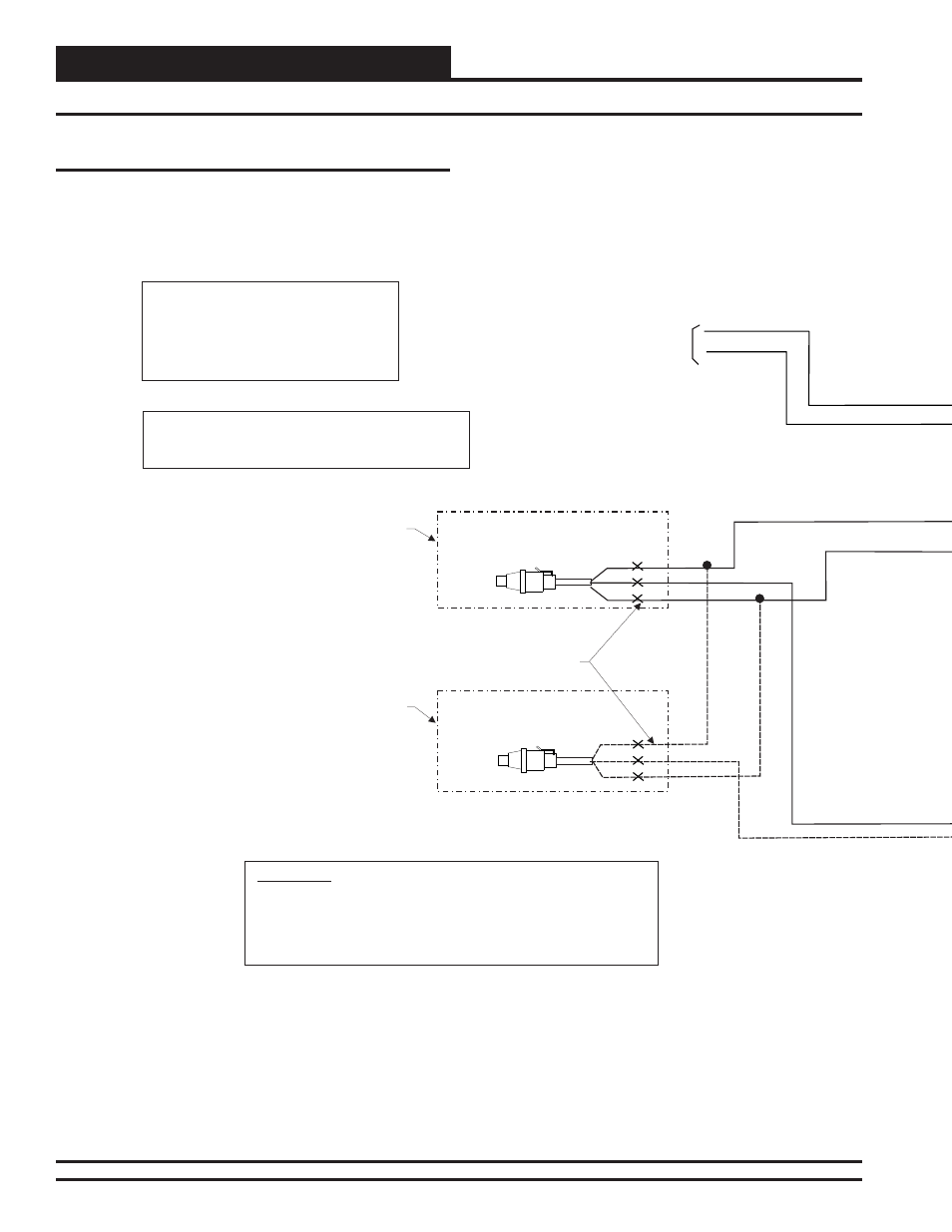
Note:
1.) Suction Pressure Transducer(s) Are Only Required For
Installations With The Dehumidification Option Installed.
Caution:
1.) The Schraeder Port Used For Installation
Of The Suction Pressure Transducer Should
Be Located In A Vertical Portion Of The
Suction Line To Prevent Refrigerant Oil From
Accumulating In The Sensor.
24 VAC
GND
10 VA Minimum Power
Required
For SA Expansion Module
Splice Wire As Required To
Reach From Transducer
Location To Expansion Module
Location
BK
BK
RD
RD
WH
WH
OE275-01
Suction Pressure Transducer
OE275-01
Suction Pressure Transducer
Wiring For Single
Cabinet Unit
Additional Wiring
For Dual Cabinet
Units
WARNING!!
Observe Polarity! All boards must be wired with GND-to-GND and 24VAC-to-
24VAC. Failure to observe polarity will result in damage to one or more of
the boards. Expansion Module must be wired in such a way that the
expansion module and the controller are always powered together. Loss of
power to the expansion module will cause the controller to become
inoperative until power is restored to the expansion module.
Digital Scroll Compressor Wiring
For Digital Scroll Applications, the Modulating Cooling Signal(s) must
be confi gured for a 1.5-5.0 VDC output signal when programming the
controller. This signal output would be connected to a Digital Scroll
Compressor Controller.
For Digital Scroll Compressor wiring details, see Figure 24 below.
Modulating Cooling Device Wiring
Figure 24: Digital Scroll Compressor Wiring