Installation & wiring, Supply fan vfd signal, Zone – Orion System SA E-BUS Controller User Manual
Page 18
Zone
Zone
Installation & Wiring
SA E-BUS Controller Technical Guide
18
Supply Fan VFD Signal or Zoning
Bypass Damper Actuator Signal
The Supply Fan VFD or Zoning Bypass Damper Actuator Signal is a
0-10 VDC output from AO2 on the SA E-BUS Controller. This signal
output can be connected to the Supply Fan Variable Frequency Drive to
modulate the Supply Fan speed and control Duct Static Pressure utilizing
the Duct Static Pressure Sensor connected to the SA E-BUS Controller.
Alternatively, it can be connected to a Zoning Bypass Damper Actuator
that will modulate the Zoning Bypass Damper Actuator to control Duct
Static Pressure utilizing the Duct Static Pressure Sensor connected to the
SA E-BUS Controller. A Duct Static Pressure Sensor must be connected
in order for the VFD or Zoning Bypass Damper Actuator to operate. See
Figures 14 and 15 for detailed wiring.
Supply Fan VFD Signal
Caution: Variable Frequency Drive units can cause large transient
noise spikes which can cause interference to be propagated on other
electronic equipment. Use shielded wire wherever possible and route
all sensor and controller wiring away from the Variable Frequency
Drive and the HVAC Unit electrical wiring.
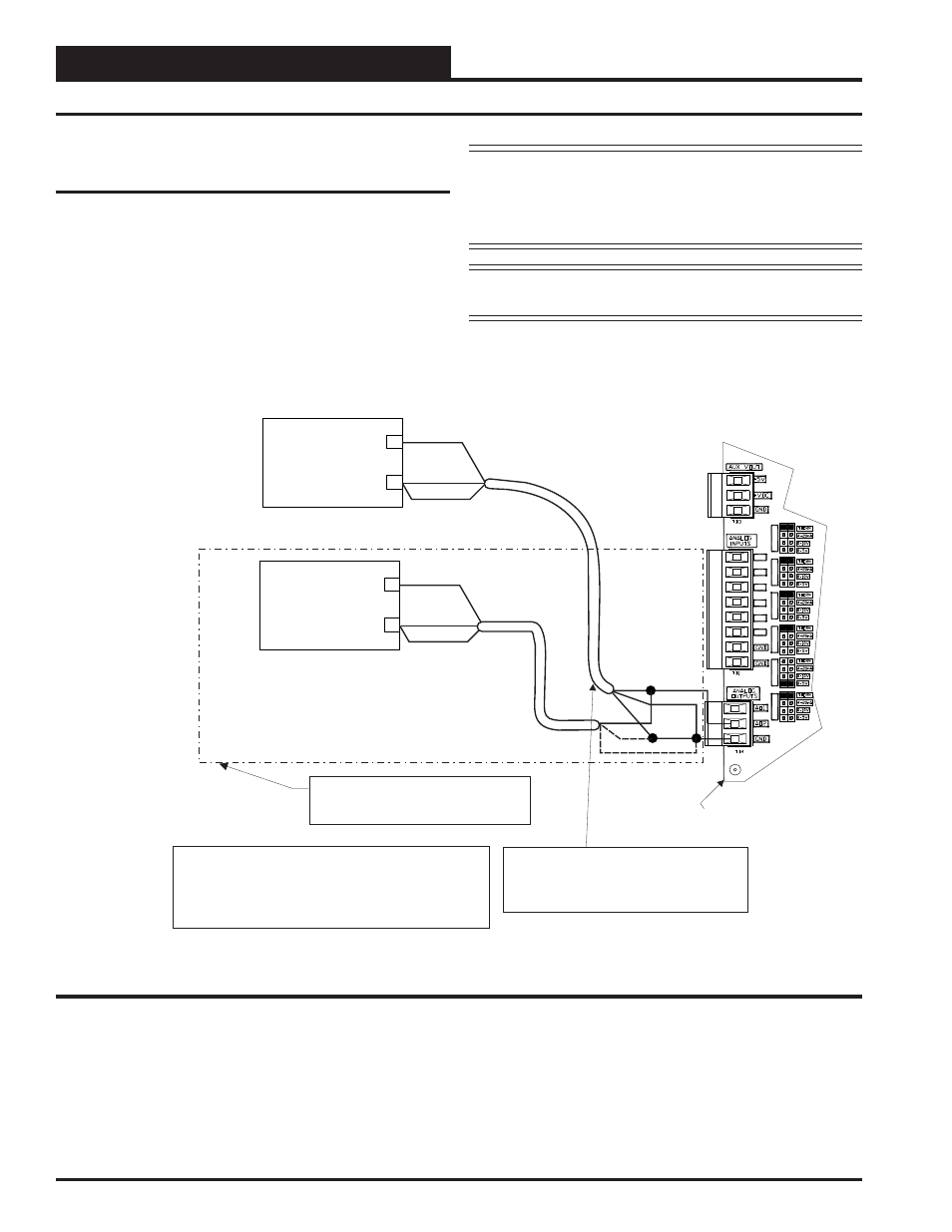
NOTE: For Dual Cabinet Units, VFD #2 must be wired in
parallel to VFD #1 as shown in Figure 14 below.
+
+
Supply Fan Variable Frequency Drive #2
(By Others)
Supply Fan Variable Frequency Drive #1
(By Others)
_
_
0-10 VDC Input From AO2
0-10 VDC Input From AO2
Shield
Shield
GND
GND
Caution:
The VFD Unit Must Be Configured For 0-10 VDC Input.
The Input Resistance At The VFD Must Not Be Less
Than 1000 Ohms When Measured At The VFD
Terminals With All Input Wires Removed.
Note:
Wire To The VFD Using 18 GA Minimum 2
Conducter Twisted Pair With Shield Cable.
Wire Shield To GND As Shown
AO2
GND
Shield
SA E-BUS Controller
AI1
AI1 SET
A
I2 SET
AI3 SET
AI4 SET
A
I5 SET
AI7 SET
AI2
AI3
AI4
AI5
AI7
Note: Required For Dual SA Unit
Applications Only.
Figure 14: Supply Fan VFD Wiring