OnLine Power Signal Saver IPC User Manual
Page 36
6002-1842 Rev A ECO# 8881
26
• PTS: BBS sends a 48VDC signal from battery to the PTS, which activates the PTS, resulting in transfer from
Input Power to Battery Power. See manual section 1.4 Wiring, for connection instructions.
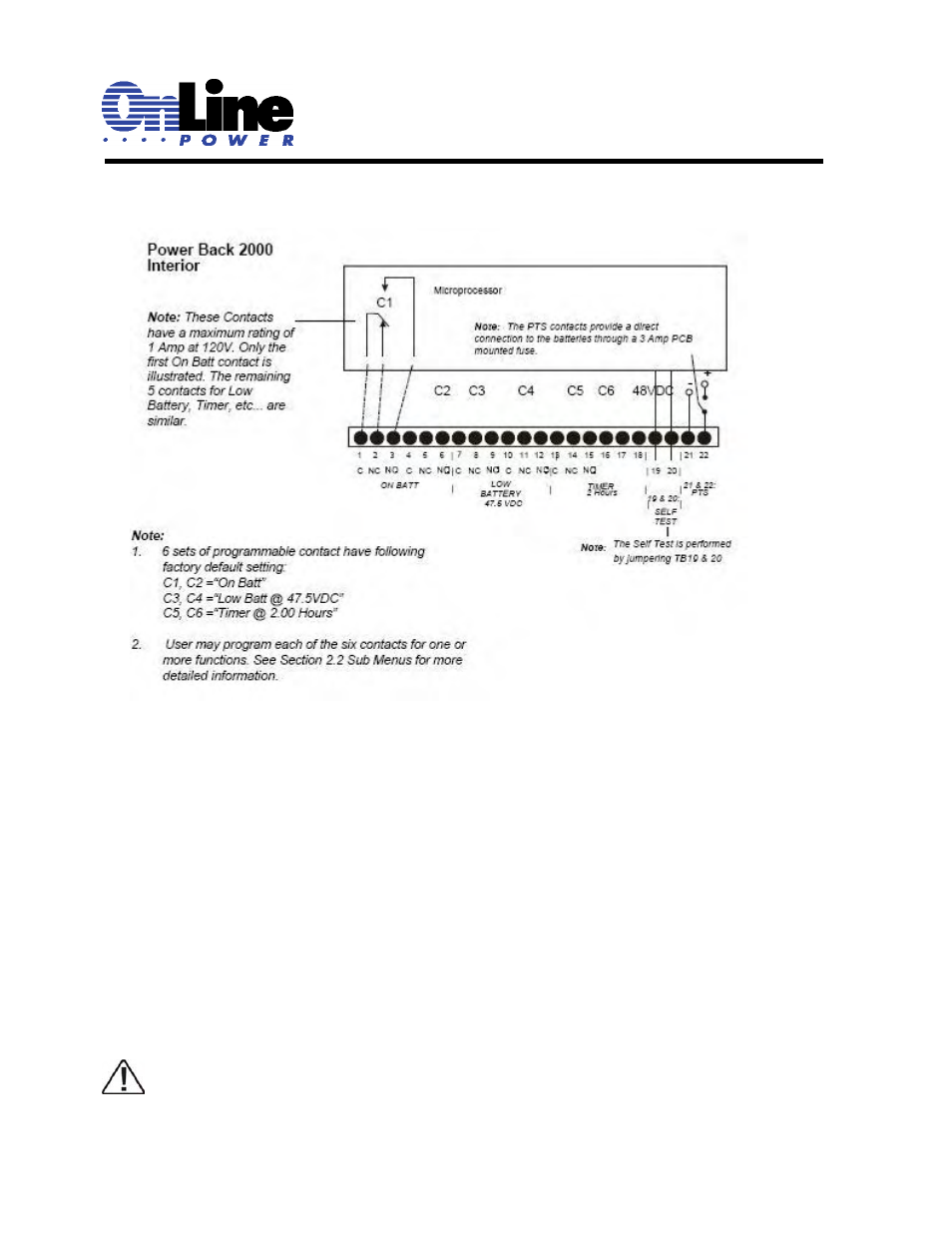
Figure 7
Green Control Terminal Block, Layout and Operation
11 Battery Temperature Sensor:
The battery temperature probe attaches to the unit at this plug. The charging voltage is temperature
dependent. The microprocessor on the smart charger adjusts the voltage for optimum charging. The probe
connector must be plugged in for normal operation. The sensor end should be firmly attached to the case of
the middle or top battery with high strength tape.
12 External Fan 48VDC:
Provides DC Power (48VDC, 4 Amp Max), which could be used to power an optional 48VDC fan
mounted inside the enclosure for regulation of the interior temperature during power outages.
13 Internal Fan:
Microprocessor-controlled fan regulates the unit’s internal temperature. It must not be blocked. The filter in
front of the fan is removable for cleaning.
TIP: Inspect the filter every 6 months or as often as required. Clean it by removing and running water
through the filter and air-drying before reinstallation.