6 shut down, Danger, 1 ups control unit shutdown – OnLine Power Signal Saver IPC User Manual
Page 23: Mbs/ptr unit, Bbs unit, Step 3, Step 2, Step 4 step 5 step 6, Step 1
6002-1842 Rev A ECO# 8881
13
1.6
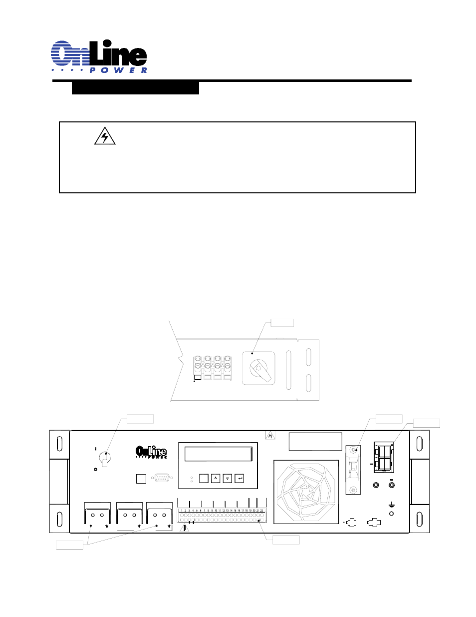
SHUT DOWN:
1.6.1 UPS control unit Shutdown:
Step 1.
Put the By-Pass Switch in the MBS/PTR box is in the “BYPASS”
Position.
Step 2.
Turn off the battery circuit breaker.
Step 3.
Turn off the input circuit breaker.
Step 4.
Unplug the 48V EXT battery connector from the unit.
Step 5.
Disconnect the PTR control signals by un-plugging the
J2/P2
Step 6.
Disconnect the input and output wires from AC INPUT & AC OUTPUT
terminal block of the BBS unit. and isolate the wires individually using
electrical tape.
This completely removes the wire from the BBS unit.
It is now safe to remove the unit for maintenance.
MBS/PTR UNIT
Read the Operator's
N
L
N
L
L
N
AC INPUT
or servicing
Manual Before Installation
AC OUTPUTS
EXTERNAL FAN
48VDC 3A MAX
Sensor
Battery temperature
BREAKER
CIRCUIT
& OUTPUT
AC INPUT
Warning
46.2lbs, 21Kg
Heavy Object
C; COMMON NC:NORMALLY CLOSED NO:NORMALLY OPEN
NO
STEP 3
NC
C2
USB
ALARM
OUTPUT
SERIAL INTERFACE
C
NO
NC
C
C1
2
1
PTS
ESC
-
TEST
SELF
CONTACTS MAXIMUM RATING: 1A, 240V
NC NO
C
C
NO
NC
C
NC NO
NO
NC
C
C6
C5
C4
C3
+
STEP 2
CONNECTOR
TEST POINT
BATTERY VOLTAGE
+
+
BREAKER
CIRCUIT
+
48V BATTERY
BATTERY
STEP 4
STEP 5
STEP 6
BBS UNIT
DANGER!
Even when the unit is off, there are potentially dangerous voltages
within the unit due to the batteries and line power connection.
Exercise extreme care when working within the BBS system.
MANUAL BYPASS SWITCH
CABINET
POWER
GND
UTILITY
LINE
NEU
AC TO
323
3
TB1
1
2
4
BBS
BYPASS
STEP 1