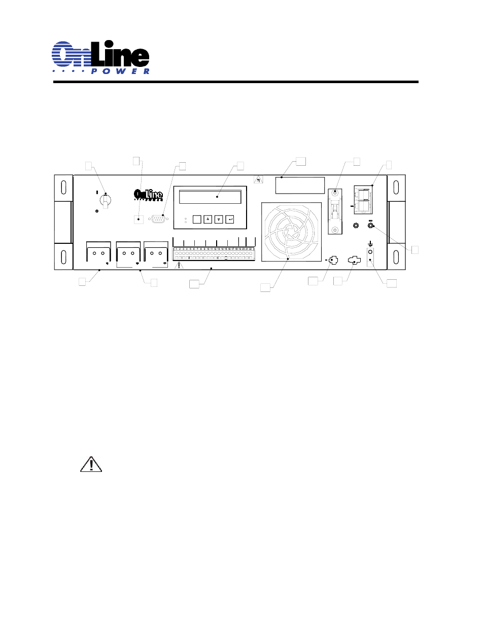
Figure 2.1, 1 48vdc battery connector, 2 battery circuit breaker – OnLine Power Signal Saver IPC User Manual
Page 34: 3 battery voltage test points, 4 liquid crystal display (lcd) and touch pad, 5 ac input & output circuit breaker, 6 ac output, The power transfer switch
6002-1842 Rev A ECO# 8881
24
2.1.2
QUICK OVER VIEW OF BATTERY BACKUP SYSTEM:
Purpose: Describes the various controls connectors and switches on the unit front panel.
Figure 2.1
1 48VDC Battery Connector:
Connects the battery string to the unit. The battery string voltage is 48VDC.
2 Battery Circuit Breaker:
Acts as an ON/OFF switch for battery power. It must be in the ON position for normal operation.
3 Battery Voltage Test Points:
Battery Voltage can be measured at these test jacks only when the battery circuit breaker is turned
ON.
TIP: Test jacks are not DC power outlet terminals and cannot provide any significant DC
amps.
4 Liquid Crystal Display (LCD) and Touch Pad:
The UPS can be controlled and monitored via the LCD Panel. See Section 2.2 for further information.
5 AC Input & Output Circuit Breaker:
Acts as a line and output power ON/OFF switch to facilitate the unit’s maintenance or replacement.
It must be in the ON position for normal operation.
6 AC
Output:
Two sets of Terminal Blocks are provided for AC output at least one of which is the “FROM UPS
OUT” cable to
the Power Transfer Switch.
SERIAL INTERFACE
7
6
5
L
9
USB
AC INPUT
& OUTPUT
CIRCUIT
BREAKER
AC OUTPUTS
AC INPUT
N
L
N
1
L
N
2
15
10
13
4
CONTACTS MAXIMUM RATING: 1A, 240V
C; COMMON NC:NORMALLY CLOSED NO:NORMALLY OPEN
8
OUTPUT
ALARM
ESC
C2
NC
Manual Before Installation
or servicing
Read the Operator's
C1
C
NC NO
C
NO
C3
C4
NC
C
C
NO
NC
NO
C5
NO
NC
C
46.2lbs, 21Kg
Heavy Object
Warning
SELF
TEST
C6
C
NC NO
-
PTS
+
12
11
14
48V BATTERY
CONNECTOR
TEST POINT
BATTERY VOLTAGE
2
+
BATTERY
CIRCUIT
BREAKER
+
+
48VDC 3A MAX
EXTERNAL FAN
Battery temperature
Sensor
3
1