Utility, Line, Complete installed unit: (shown with 332a cabinet) – OnLine Power Signal Saver IPC User Manual
Page 21: Figure 1.7, Batt, 332 cabinet, Line neutral gnd, External cabinet, Mbs/ptr
6002-1842 Rev A ECO# 8881
11
BBS UNIT
+
BATT
11
BATT
+
1
1
-
2
3
2
3
44
-
3
4
2
3
4
2
J2
/P
2
BATT
BATT
+
2
2
HARNESS 7060-1162-01
+
1
1
-
4
3
4
3
J3
/P
3
22
-
3
3
J4
/P
4
44
1
1
J1
/P
1
G BUS
332 CABINET
L
UTILITY
LINE
NEUTRAL
GND
LINE
EXTERNAL CABINET
HARNESS 7060-1163-01
AC OUTPUT
UTILITY LINE IN
HARNESS 7060-1090-01
N BUS
N
G
HARNESS 7060-1164-01
NEU
7060-1091-01
HARNESS
MBS/PTR
GND
AC INPUT
& OUTPUT
CIRCUIT
BREAKER
AC INPUT
N
L
48V BATTERY
CONNECTOR
Battery temperature
Sensor
C; COMMON NC:NORMALLY CLOSED NO:NORMALLY OPEN
1
2
L
N
C
SERIAL INTERFACE
L
N
AC OUTPUTS
USB
C3
C4
C5
C6
C
NC
NO
NC
C
NC NO
C
C
NO
NC
CONTACTS MAXIMUM RATING: 1A, 240V
ESC
C1
C2
C
NO
NC
NC NO
OUTPUT
ALARM
Read the Operator's
Manual Before Installation
or servicing
+
NO
SELF
TEST
-
PTS
48VDC 3A MAX
EXTERNAL FAN
+
Heavy Object
46.2lbs, 21Kg
Warning
+
BATTERY
CIRCUIT
BREAKER
+
BATTERY VOLTAGE
TEST POINT
J2
P2
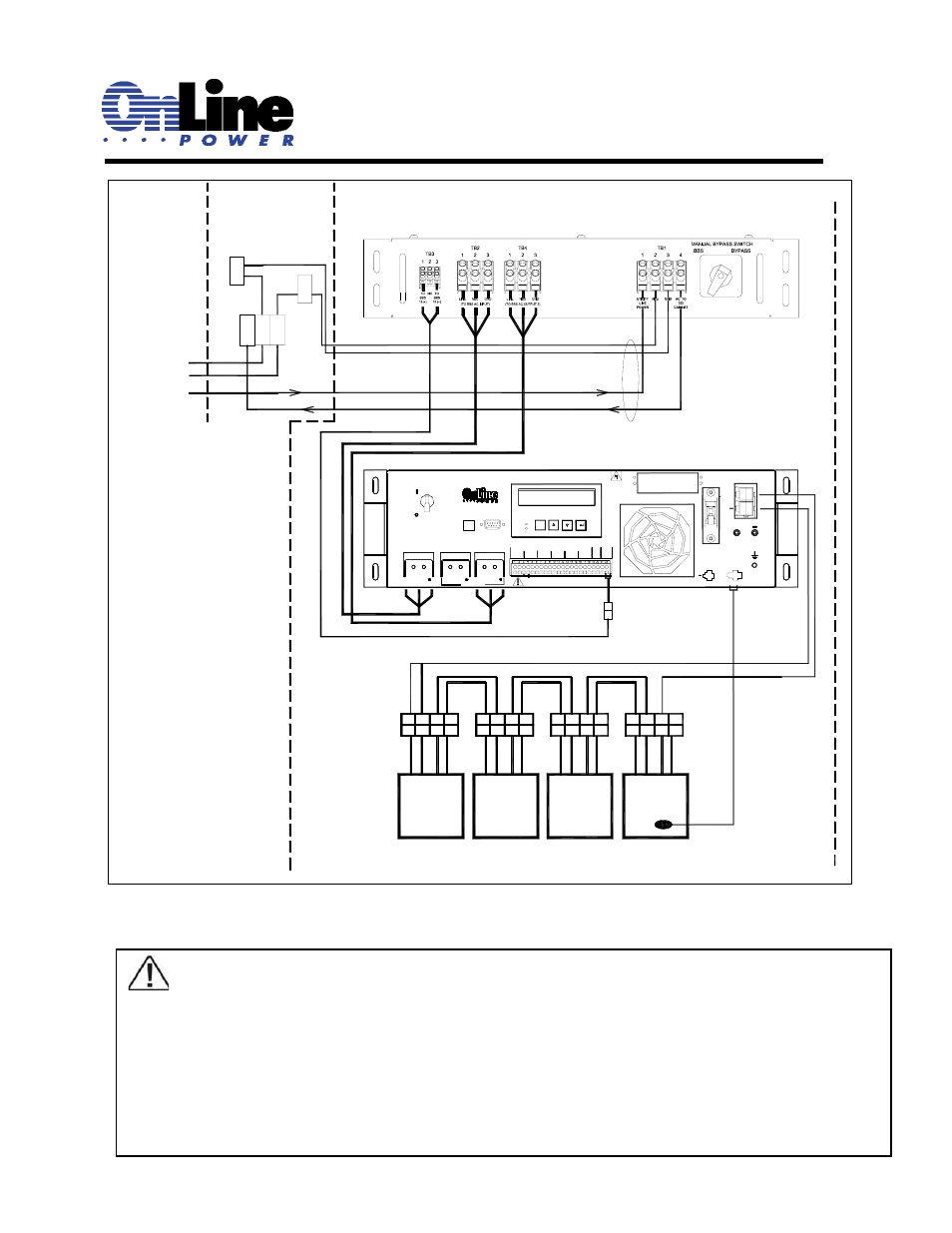
Complete Installed unit: (Shown with 332A cabinet)
Figure 1.7
.
TIP:
Each of the six contacts are of form C type, meaning Normally Open (NO), common (C) and Normally Closed
(NC) dry contact rated for 1 Amp at 120VAC. Each of these contacts can be individually programmed to
energize and stay latched for ON BATTERY, LOW BATTERY, TIMER, ALARM, FAULT and many other
conditions as described in subsequent chapters. The ON BATTERY contact(s) are activated as soon as the
BBS is transferred to Battery mode. LOW BATTERY contact(s) are activated only in the Battery mode as
soon as the discharged battery reaches the lower value battery capacity as set by user and remains latched
as long as the system remains in Battery mode. The TIMER contact(s) are activated only in the Battery mode
after the user-programmed time is attained, that can be set in 15-minute intervals from 15 minutes to 8 hours.