Batt, Bbs unit, 1j2/ p2 – OnLine Power Signal Saver IPC User Manual
Page 20: 11 j3/ p3, 1j4/ p4, 1j1/ p1
6002-1842 Rev A ECO# 8881
10
44
AC INPUT
& OUTPUT
CIRCUIT
BREAKER
AC INPUT
N
L
48V BATTERY
CONNECTOR
Battery temperature
Sensor
C; COMMON NC:NORMALLY CLOSED NO:NORMALLY OPEN
1
2
L
N
C
SERIAL INTERFACE
L
N
AC OUTPUTS
USB
C3
C4
C5
C6
C
NC
NO
NC
C
NC NO
C
C
NO
NC
CONTACTS MAXIMUM RATING: 1A, 240V
ESC
C1
C2
C
NO
NC
NC NO
OUTPUT
ALARM
Read the Operator's
Manual Before Installation
or servicing
+
NO
SELF
TEST
-
PTS
48VDC 3A MAX
EXTERNAL FAN
+
Heavy Object
46.2lbs, 21Kg
Warning
+
BATTERY
CIRCUIT
BREAKER
+
BATTERY VOLTAGE
TEST POINT
4
4
44
BATT
+
1
1
J2/
P2
-
3
3
2
2
4
4
+
11
J3/
P3
-
3
3
BATT
2
2
+
1
1
J4/
P4
-
3
3
BATT
22
BBS UNIT
HARNESS 7060-1162-01
+
1
1
J1/
P1
-
3
3
BATT
2
2
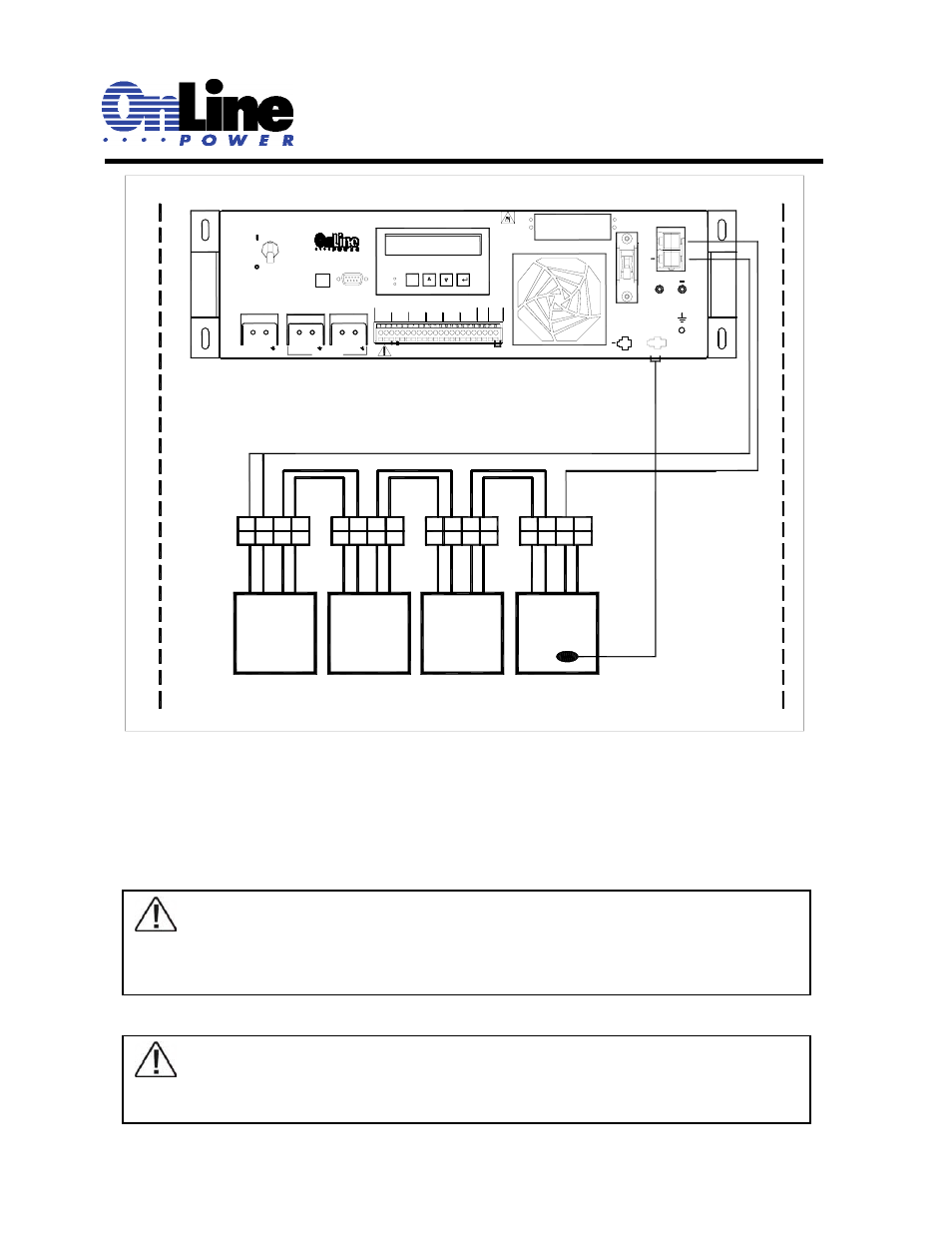
Interconnection between Battery and UPS Control unit
Figure 1.6
♦ Tape or seal the Battery Temperature Sensor to the case of the top battery. Plug the connector on the
other end into the BBS at “Battery Temperature Sensor”. Wrap a tie around the strain relief loop and
the battery temperature sensor to prevent the connector from disconnecting during an earthquake or
other severe vibrations.
TIP: The 48V BATTERY CONNECTOR must ‘click’ when inserted for proper connection.
A common source of problems is that the battery connector is not fully inserted. The BBS will
Alarm when turned on if the batteries are not properly connected.
NOTE: The LCD Display and keypad on the BBS are shipped with a protective plastic film
over them. This film should be removed by peeling from one corner before first use of the
system. The LCD display will be difficult to read if the film is left on.