Installation – Montigo H34DL User Manual
Page 6
H-Series DL Indoor Gas Fireplace
Page 6
XG0140 - 070714
Installation
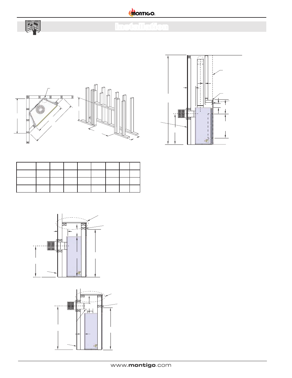
Section 2: Framing
1).
Frame in the enclosure for the unit with framing materials. The
framed opening for the assembled fireplaces are as shown below,
see Figure 2
.
NOTE: When constructing the framed opening, please ensure there is
access to install the gas line when the unit is installed. See Figure 26.
(When sheetrock is not used behind
the fireplace, framing depth "O" may be
reduced by 5/8".)
0" clearance
to corners only
P”
N”
Q”
N”
M”
O”
Figure 2. Framing dimensions for Straight wall and Corner Installation.
Figure 4. Combustible Framing for shelves over the fireplace, Top vent.
Figure 3. Combustible Framing for shelves over the fireplace, Rear vent.
L
M
N
O
P
Q
S
T
H*34DL*
25
37 1/4 33 3/4 17 7/8 52 3/8
37
31
41
H38DL* 27
3
/
4
40 1/4 37 3/4 18 7/8 57 1/2 40 5/8 34
44
H42DL* 31
1
/
2
44 1/4
42
19 3/8 63 3/4 45 1/8 38
48
† See Vent Graph for
minimum measurement
requirements figures
11, 12 or 13.
†
Figure 5. Non Combustible Framing for Top Vent or Rear Vent, with Alcove
ABOVE FIREPLACE.
Min.
96”
12”
door
opening
3”
Rear
Vent
Floor
Top Vent
18”
max.
2”
min.
Non-combustible
header
Min 1”
L
Exterior
Wall
Ceiling level
Non-Combustible
materials. Alcove
over fireplace.
Non-combustible
Facing materials.
M
9”
S
L
18”
max.
2” min.
Combustible
Header
Combustible
Shelf
Exterior
Wall
L
PEL Shor t
90° elbow
M
17 1/2”
2” min.
Combustible
Header
Combustible
Shelf
Exterior
Wall