Installation, Warning – Montigo H34DL User Manual
Page 14
H-Series DL Indoor Gas Fireplace
Page 14
XG0140 - 070714
Installation
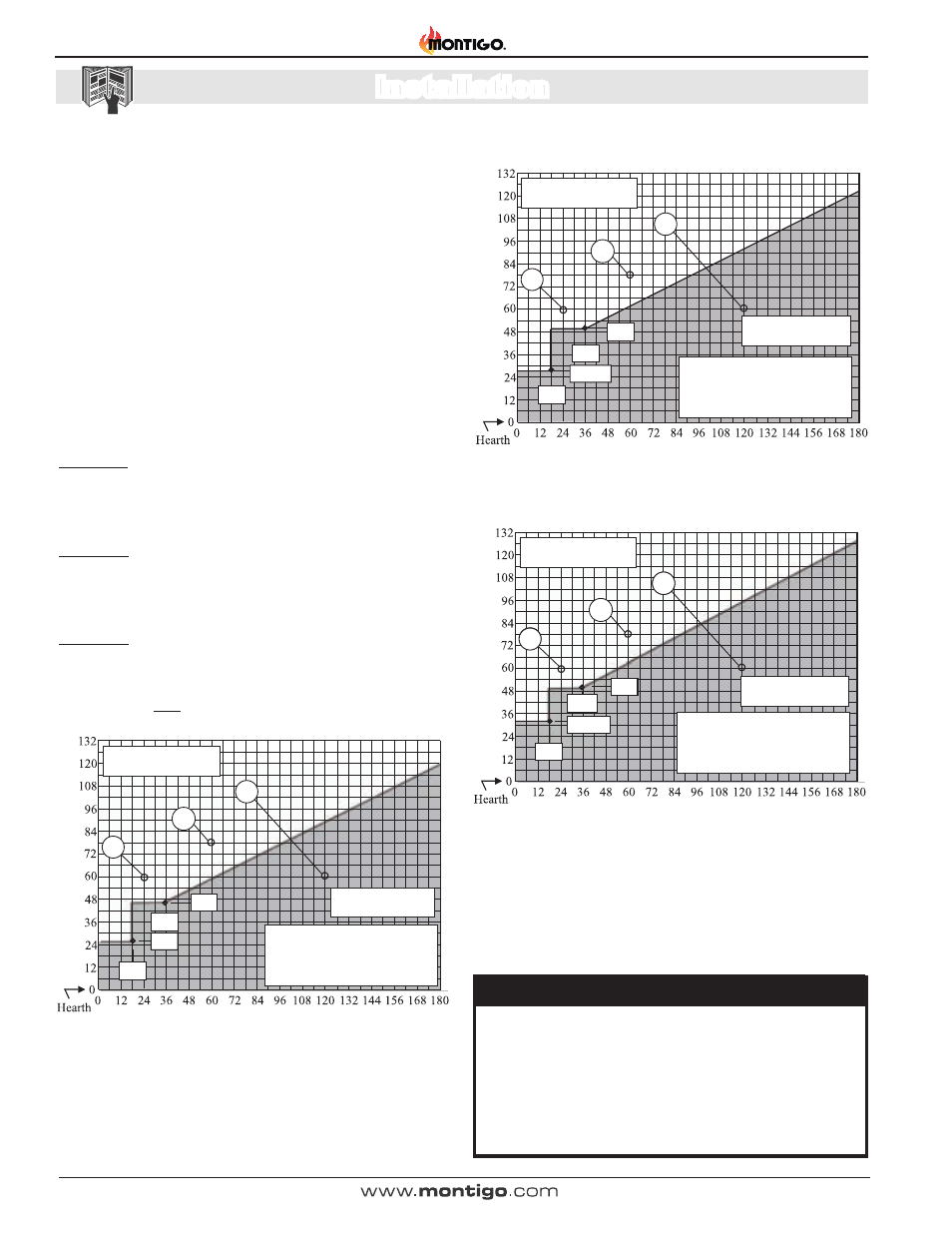
Figure 15. H*34DL* Rear Vent Venting Graph for wall mounted terminations,
See Figures 18a & 18b.
Notes Wall Mounted Terminations: REAR VENT
All dimension lengths for vertical or horizontal runs are measured
from center of the vent pipe.
Venting runs must fall within the limits set by the venting graphs,
see Figure 15, 16 or 17.
Fireplace must be converted to Rear Vent configuration prior to
running vent, see Figure 7 and 7a.
The Venting Graph
Measure the vertical height from the fireplace hearth to the centre of
the termination and the horizontal run from the fireplace flue collar to
the wall flange of the termination. Plot on the Venting Graph Figure 15,
16, or 17 with an 'X'.
If the 'X' falls on or above the top boundary of the shaded area, the
installation is acceptable.
Example A: (Acceptable Installation)
If the vertical dimension from the hearth is 60" and the horizontal
run to the wall flange of the vent termination is 24", this would be
an acceptable installation.
Example B: (Acceptable Installation)
If the vertical dimension from the hearth is 78" and the horizontal
run to the wall flange of the vent termination is 60", this would be
an acceptable installation.
Example C: (Unacceptable Installation)
If the vertical dimension from the floor of the fireplace is 60" and
the horizontal run to the wall flange of the vent termination is 120",
this would NOT be an acceptable installation.
Figure 16 H38DL* Rear Vent Venting Graph for wall mounted terminations,
See Figures 18a & 18b.
18”
25”
A
C
B
Horizontal Run (in.)
Ve
rt
ical Height (in.)
36”
46”
Acceptable Vent run
within non-shaded area.
Acceptable vent run
within non-shaded area.
WARNING:
An inspection of the explosion relief flappers and door
MUST be made prior to lighting the fireplace. Faulty seal
on the door gasket and/or explosion ports will result in
products of combustion leaking into the living space and
may result in carbon monoxide poisoning.
If your installation does not fall
within the venting graph parameters,
please contact a local Montigo
dealer for Power Venting options.
Figure 17 H*42DL* Rear Vent Venting Graph for wall mounted terminations.
Straight off the back Natural Gas ONLY. See Figures 18a & 18b.
Horizontal Run (in.)
Ve
rt
ical Height (in.)
18”
36”
50”
31 1/2”
A
C
B
Unacceptable vent run
within shaded area.
Acceptable vent run
within non-shaded area.
If your installation does not fall
within the venting graph parameters,
please contact a local Montigo
dealer for Power Venting options.
18”
27 3/4”
A
C
B
Horizontal Run (in.)
Ve
rt
ical Height (in.)
36”
50”
Unacceptable vent run
within shaded area.
Acceptable vent run
within non-shaded area.
If your installation does not fall
within the venting graph parameters,
please contact a local Montigo
dealer for Power Venting options.