Measurement Computing CIO-PDMAxx User Manual
Page 20
The data in the counter read register, and the action taken on the data in the counter
load register, is wholly dependent upon control code written to the control register.
The counters are 16 bits, each with an 8-bit window, the read/load register. Data are
shifted into and out of the 16-bit counters through these 8-bit windows according to
the control byte.
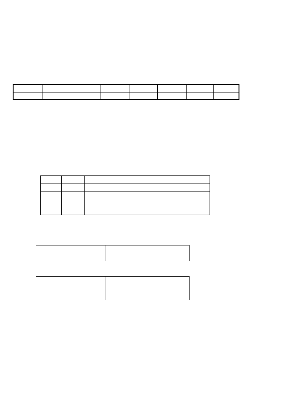
5.2.5 Counter Control Register
Base Address + 7
LSB
MSB
BCD
M0
M1
M2
RL0
RL1
SC0
SC1
0
1
2
3
4
5
6
7
SC1 and SC0 are the counter select bits. The are binary coded between 0 and 2.
SC1
SC2
Counter
0
0
0
0
1
1
1
0
2
RL1 and RL0 are the read and load control bits:
Read/load low then high byte (word transfer).
1
1
Read/load low byte.
0
1
Read/load high byte.
1
0
Latch counter.
0
0
Operation
RL0
RL1
M2 to M0 are the counter mode control bits:
Counter 0 and Counter 1 are hardware-fixed to operate in Rate Generator mode only.
Rate Generator.
0
1
0
Operation Type
M0
M1
M2
Counter 2 can support the following two modes:
Rate Generator.
0
1
0
Change on terminal count.
0
0
0
Operation Type
M0
M1
M2
BCD = 0: The counters are hardware fixed to support 16-bit binary mode only.
16