2 cio-pdma32 register map – Measurement Computing CIO-PDMAxx User Manual
Page 17
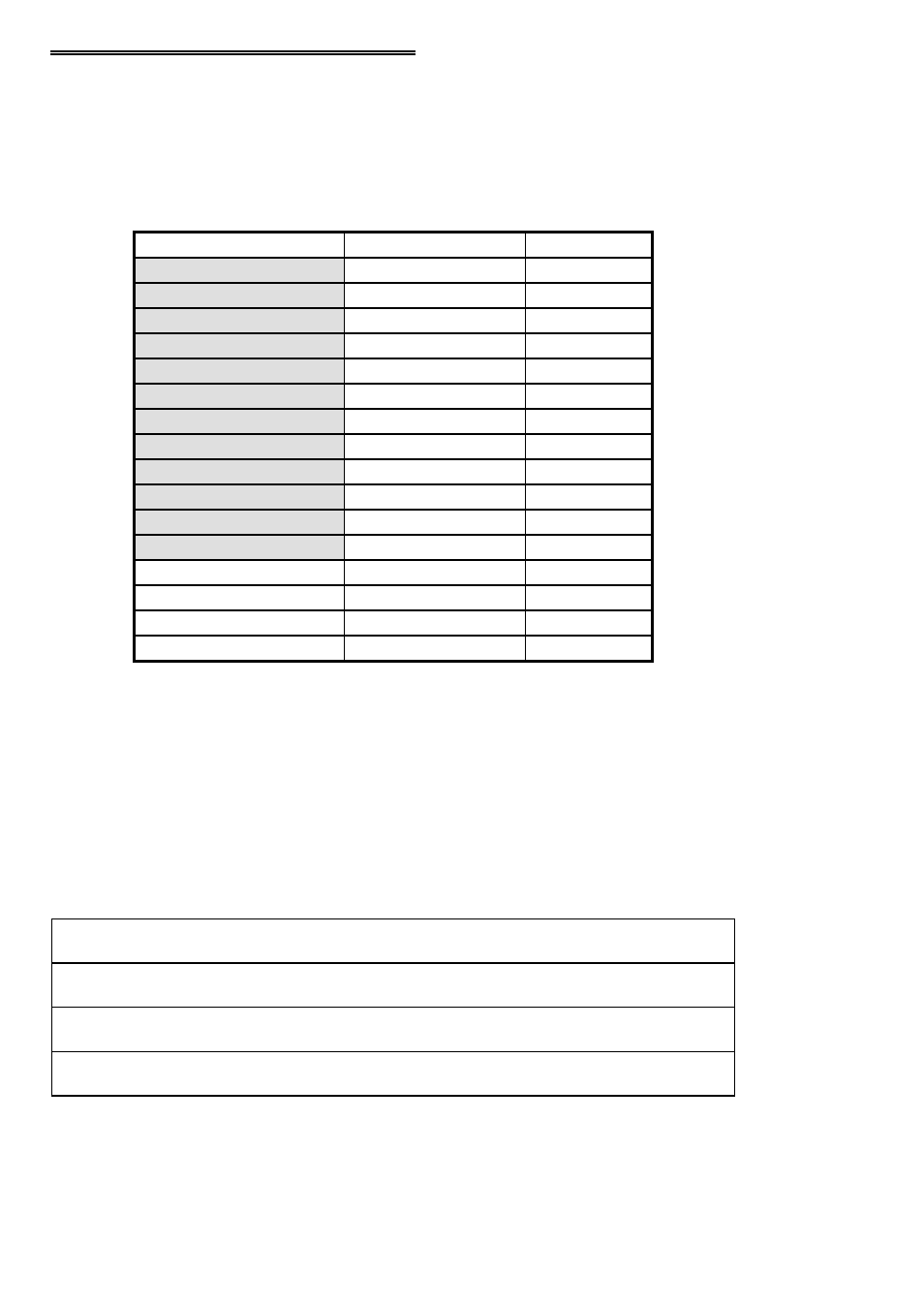
5.2 CIO-PDMA32 REGISTER MAP
The PDMA-32 boards use 16 consecutive addresses starting at the Base Address in
the computers I/O space, as shown in the following table. The shaded areas highlight
the address space that the MetraByte PDMA-32 board uses. Note that MetraByte does
not use Addresses B to F hex.
Read/write
FIFO
Base Address + E : F
Write
Arm
Base Address + D
Read/Write
REP Control
Base Address + C
Write
FIFO Clear
Base Address + B
Read
Interrupt Status
Base Address + A
Read/write
Interrupt Level
Base Address + 9
Read/write
DMA Level
Base Address + 8
Read
Counter Status
Write
Counter Control
Base Address + 7
Read/write
Counter 2
Base Address + 6
Read/write
Counter 1
Base Address + 5
Read/write
Counter 0
Base Address + 4
Read/write
Interrupt Control
Base Address + 3
Read/write
DMA Control
Base Address + 2
Read/write
B Port
Base Address + 1
Read/write
A Port
Base Address + 0
TYPE
FUNCTION
ADDRESS
5.2.1 PORTS A & B Base Address + 0 and Base Address + 1
These ports are the main digital I/O ports. Each port is 8-bits wide and can be used
individually or combined into one 16-bit port for programmed I/O, DMA I/O, or
rep-string I/O. Each port is associated with a data direction output (ADIR, BDIR).
Bits D0 and D1 of the DMA Control register select the data directions. On power-up,
ports are always reset to the Input mode.
B Irrelevant
Word for DMA or Rep-String
A controls both ports
Word for I/O
5-7 (Word)
1-Word
B Irrelevant
Word for DMA or Rep-String
A controls both ports
Byte for I/O
5-7 (word)
0-Byte
B Irrelevant
Byte (PA) for DMA or Rep-String
A controls both ports
Word for I/O
0-3 (byte)
1- Word
Byte for DMA or Rep-String
A & B Independent
Byte for I/O
0-3 (byte)
0-Byte
A & B Direction
Port I/O
DMA Level
Bit D2
13