Measurement Computing CIO-PDMAxx User Manual
Page 18
Byte-wide DMA or Rep-String operations may be made only through Port A. If byte
mode is selected via the DMA Control Register (D2=0), then Port B is available and
independent of Port A for input or output using programmed I/O.
When word mode is selected via the DMA Control Register (D2=1), then the data
direction of Port B always follows the data direction of Port A.
Word-wide DMA or Rep-String operations are made through both Ports A and B
combined. In word mode, Port A provides the LSB and Port B the MSB of data. The
data direction of both ports has to be identical if a Word transfer DMA or Rep-string
(Level 5-7) is selected, and the B direction bit (D1 of the DMA Control Register), is
ignored both for DMA and Programmed I/O.
For normal Programmed (non-DMA) I/O, you have a choice of accessing the ports as
two separate byte-wide ports or configuring them as a single 16-bit word-wide port.
Notes:
1.
Both ports are automatically set up in the input direction on power-up.
2.
In Input mode, each line of Port A and B presents one TTL load to the driving
source. In Output mode, outputs of both ports will sink 24 mA and are TTL
compatible.
3.
In Output Mode, data can be read back from either Port. This data corresponds to
the actual data on the output pins and may not correspond to data written if an
output line is shorted or faulty.
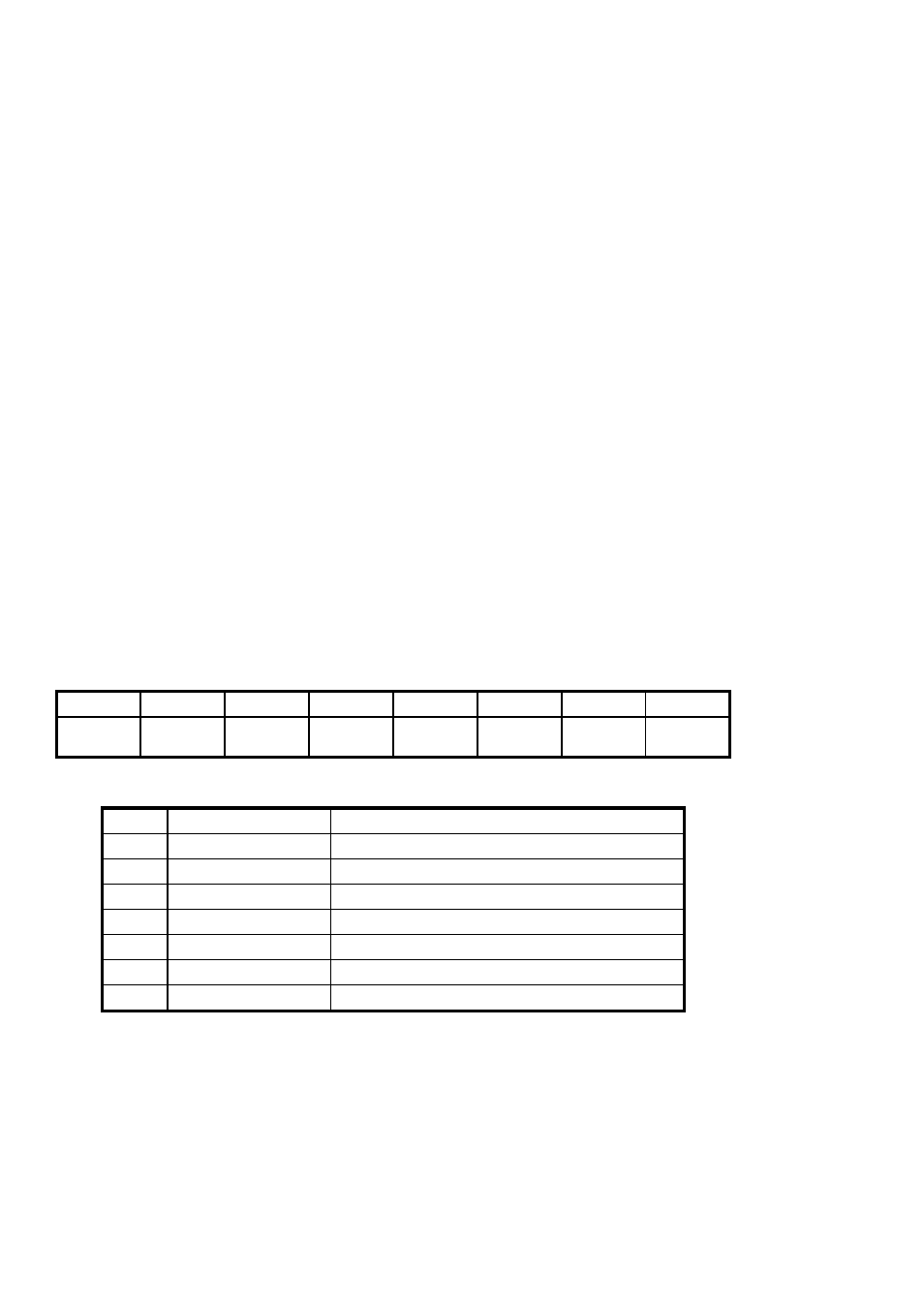
5.2.2 DMA Control Register
Base Address + 2
ADIR
BDIR
BYTE/
WORD
XFER
SRC
AUX1
AUX2
0
DMA
ENB
0
1
2
3
4
5
6
7
MSB
LSB
0 = Input, 1 = Output
ADIR
0
0 = Input, 1 = Output
BDIR
1
0 = Byte, 1 = Word
BYTE/WORD
2
0 = EXT, 1 = internal C/T
XFERSRC
3
Auxiliary user output
AUX1
4
Auxiliary user output
AUX2
5
0 = Disable, 1 = Enable
DMAENB
7
Description
Name
Bit
Notes:
1.
The DMA Control Register is cleared on power-up (reset) of the computer, thus
disabling DMA and setting the ports as inputs.
14