Functional concepts – Measurement Computing WBK17 User Manual
Page 4
WBK17, pg. 4
987996
WBK17, Counter/Encoder Module
Using Fastener Panels to Stack Modules
For convenient mounting, the WBK17 has the same footprint as other WBK modules and WaveBooks.
Fastener Panels, sometimes referred to as “splice plates,” provide a means of stacking WaveBooks and
modules. Optional screw-on handles are available for portable applications. Refer to this manual’s
introduction for assembly information.
When using WBK17 modules in conjunction with other WBK modules, the WBK17
modules must be located closest to the WaveBook due to the CA-217 cable length.
The order of the other WBK modules does not matter.
Fastener panels will partially block the vents on WBK16s and the vents on
WaveBook/512A, /516, /516A, and /516E when the units are stacked.
This partial blocking of vents does not jeopardize the cooling process.
Functional Concepts
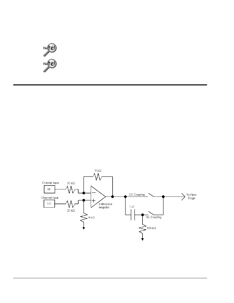
Input Coupling
Each WBK17 channel has a programmable input coupling feature. Input coupling can be turned off, or be
selected for AC or DC coupling. The type of coupling is determined after the input differential amplifier.
DC coupling makes use of the path going straight to the filter stage (of the programmable analog filter),
where as AC coupling makes use of the path with the 1 uF capacitor.
The inclusion [or exclusion]of DC offsets is important when calculating the appropriate comparator
threshold for the input waveform.
Use AC coupling to reject unwanted DC offsets. In other words, to prevent DC offsets from reaching the
comparator. AC coupling works well when the input is constantly changing. If the input stops for longer
than one second, it will appear as DC and may cause the comparator to switch on the decaying DC input.
Use DC coupling when both AC and DC components are to be presented as input to the comparator.
DC coupling does not reject anything. If the input can have periods of stability longer than one second, use
DC coupling so the comparator does not switch on a decaying DC input.
Input Coupling
The input coupling stage, shown in the figure above, is compatible with encoder outputs that have balanced
outputs (driving both high and low.) The high and low voltages are required to be within the maximum
input voltage range of –75V to +75V. A wide range of input waveforms can be accommodated since the
WBK17’s comparator threshold can be set anywhere from –12.5V to +12.5V. Many encoders offer
line driver outputs, using 4469 or 8830 driver circuits. The 8830 is a dual differential line driver with
balanced TTL outputs capable of directly driving long lengths of coax or twisted pair cable. The 4469 is a