Pattern detection and data markers – Measurement Computing WBK17 User Manual
Page 31
WBK17, Counter/Encoder Module
987996
WBK17, pg. 31
Pattern Detection and Data Markers
The WBK17 has a pattern detection feature that can be individually programmed for any of the 8 input
channels. The pattern detection feature allows up to 16 detection setpoints to be set on each channel. Each
detection setpoint can be programmed in several ways: inside the window, outside the window, above
setpoint, below setpoint. When a channel’s setpoint criteria has been met, a digital marker signal called the
detect signal will go high. The detect signals can also be part of the scan group and measured just like any
other input channel, allowing real time data analysis during an acquisition. Each setpoint can also update
the digital output port with a data byte and mask byte allowing real time control based on acquisition data.
The WBK17 pattern detection module looks at the 16-bit data being returned on a given channel and
generates another signal for each channel, Detect1 for Channel 1, Detect2 for Channel 2, etc. These signals
act like data markers for each channel’s data, whether that data is counts, period, pulsewidth, timing, or
encoder position. A channel’s detect signal will be high when the channel’s data meets any one of 16 pre-
programmed setpoint windows, the detect signal will be low when the channel’s data does not meet any of
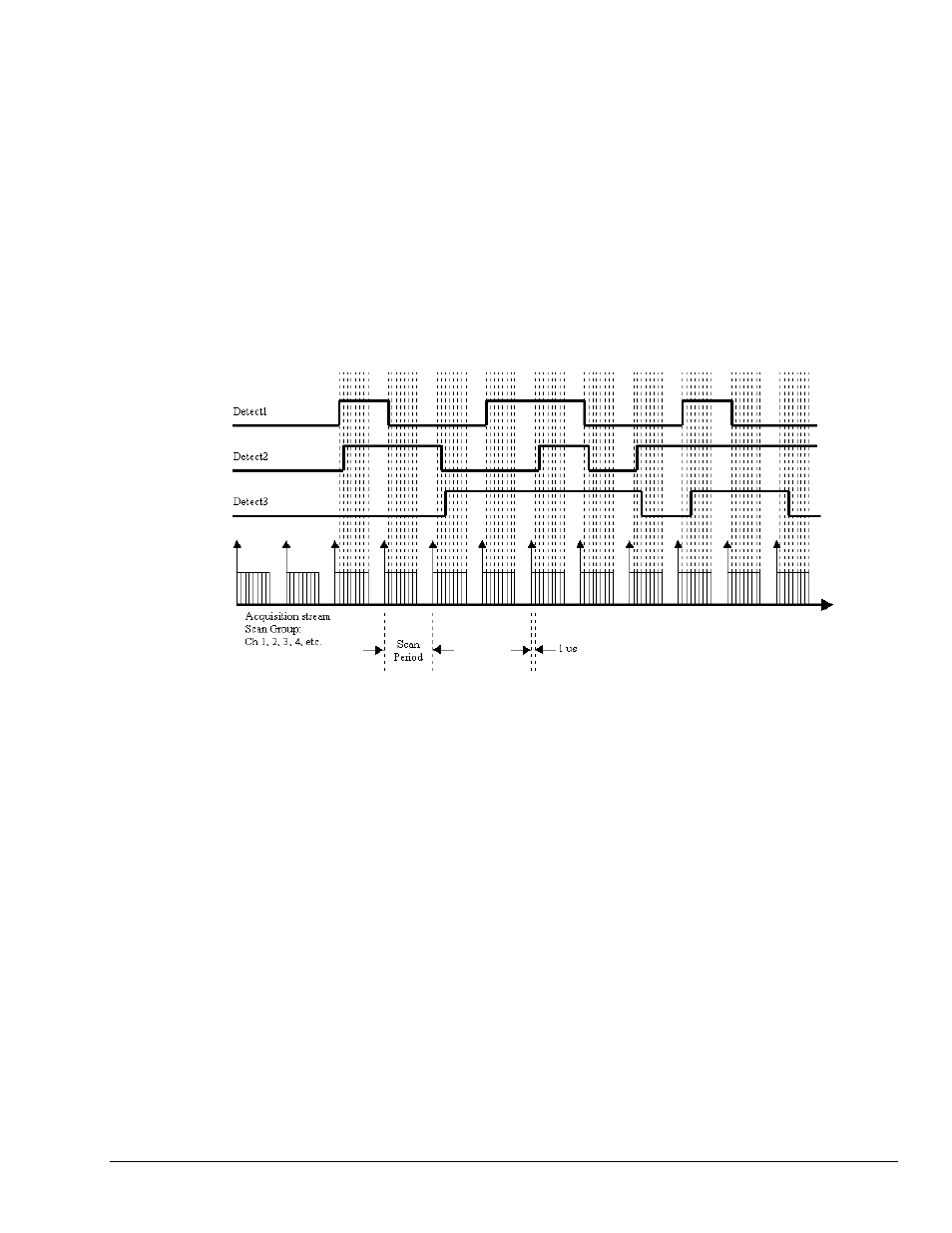
the setpoint windows. The detect signal has the timing resolution of the scan period as seen in the diagram
below. The detect signal can change no faster than the scan frequency (1/scan period.)
Example Diagram of Detection Signals for Channels 1, 2, and 3
Each channel can have 16 detection setpoints. Detection setpoints act on 16-bit data only. Since the
WBK17 has 32-bit counters for each channel, data is returned 16-bits at a time. The lower word, the higher
word or both lower and higher words can be part of the scan group. Each channel has 16 detection
setpoints for the counter’s lower 16-bit value and 16 detection setpoints for the counter’s higher 16-bit
value. Any mix of setpoints can be programmed to drive the detect signal. If all lower word setpoints and
higher word setpoints were programmed for a channel, that channel would have 32 programmed setpoints
driving the detect signal during the acquisition.
All setpoints are programmed as part of the pre-acquisition setup, similar to setting up the analog path,
debounce mode, or counter mode setup. As stated above, each setpoint acts on 16-bit data. Therefore each
setpoint has two 16-bit compare values: High Limit and Low Limit. The High Limit and Low Limit
values define the setpoint window. Each setpoint has four comparison types: (1) inside the window, (2)
outside the window, (3) greater than value, and (4) less than value. The programmed comparison type tells
the detection module how to compare the channel’s data value to the values of High Limit and Low Limit.
Each setpoint can also be programmed with an 8-bit digital output byte (DigOut) and corresponding 8-bit
mask byte (DigMask). When the setpoint criteria has been met, the digital output port can be updated with
the given byte and mask.
The digital output port can also be part of the setpoint comparison. Any setpoint can be programmed to
take the detect signal high when the digital output port is equal to the 8-bit digital byte DigComp qualified
by the 8-bit DigMask. If any of the digital output port bits are not going to be driven as outputs, they can
act as inputs that drive the detection signals via setpoints. The diagram below summarizes the comparisons
that are possible.