Measurement Computing WBK17 User Manual
Page 32
WBK17, pg. 32
987996
WBK17, Counter/Encoder Module
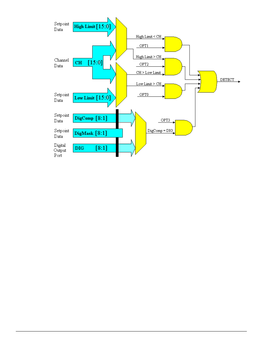
Pattern Detection Module
Note: OPT bits (see figure) are set by software options.
Example: Setpoint Detection on a Totalizing Counter
The figure below shows how 3 setpoints could be defined for channel 1. Channel 1 is shown in totalize
mode, the counter is simply counting upward. The setpoints define points of change for Detect 1 as the
counter counts upward. The first setpoint (High Limit1, Low Limit1) dictates channel 1’s detect output to
be high when greater than Low Limit1 but less than High Limit1. In this case, the channel 1 setpoint is
defined for the 16 lower bits of channel 1’s value. Channel 1 could be in 16 or 32-bit mode, the detect
pattern would just repeat every time the lower 16-bit counter rolled over. There is another setpoint set by
(High Limit2, Low Limit2), and then another set by (High Limit3, Low Limit3). The last setpoint (High
Limit3, Low Limit3) dictates that channel 1’s detect output be high whenever Channel 1’s value is greater
than HighLimit3. LowLimit3 is ignored. The digital output port could be updated on each rising edge of
Detect 1.