Measurement Computing WBK17 User Manual
Page 25
WBK17, Counter/Encoder Module
987996
WBK17, pg. 25
If more timing resolution is needed, the scan period must be shortened. This has an impact when setting a
detection setpoint because the values coming back from the acquisition have the timing granularity defined
by the scan period, not the actual counter. The counter may be counting very fast but the scan period could
be much slower, so the acquired data may only show every 10th count or every 100th count or whatever. If
the counter input is sufficiently fast and the scan period much slower, a detection setpoint could be
completely “stepped over” and go unrecognized, even though the counter clearly ran through the setpoint.
Application Example #1
Determining how many times an encoder goes beyond a certain position.
A user wants to know the number of times an encoder goes beyond a certain position. We will refer to the
position to be exceeded as “Low Limit.” To find the answer he completes the following steps.
1.
Sets a detection setpoint on Channel 1 of the WBK17 (channel 9 in the scan). The detection
setpoint will be CH1 data > Low Limit, where Low Limit is a 16-bit value.
2.
Sets channel 9 in the scan to be in Encoder Mode. Note that channel 9 is A, channel 10 is B,
and channel 11 is Z.
3.
Sets channel 12 to count the mapped channel.
4.
Sets the mapped channel to Detect1.
5.
Starts the acquisition.
In this example the setpoint criteria is simple, Ch1 data > Low Limit. Because of the criteria, whenever
the data on channel 1 goes beyond the value of Low Limit, Detect1 will go high.
Note: Detection setpoints are evaluated on a per-sample basis, for every scan. Since each channel can
have up to 16 different setpoints, the WBK17 must cycle through 16 setpoints, searching for a
match, every microsecond. The first match that is found terminates the search for that channel’s
current sample. Once the match has been found the digital output port can be updated (or NOT)
and the Detect1 signal (for channel 1) will be taken high.
The following timing diagram represents detection setpoints being used to drive a Detection signal for
channel 1.
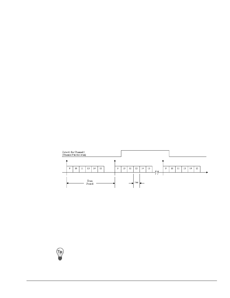
Timing Diagram with Channel Detection Signal
As shown in the diagram, Detect1 for Channel 1 (Channel 9) will go high for those samples that meet the
setpoint criteria (Ch1 data > Low Limit). Note that the Detect signal can get routed to another counter
channel and be used at that channel to clock a counter. This allows the user to count the number of times an
encoder crosses a specified boundary. As an alternative, the Detect signal’s pulsewidth could be measured,
giving the amount of time that the encoder spent beyond the setpoint criteria.
The channel’s data stream will return data indicative of the time that Detect was active high and, more
importantly, the time that the encoder’s position was within the setpoint window. Keep in mind that the
timing resolution of the Detect signal is directly related to the Scan period, not to the actual counter.
Therefore smaller scan periods result in better timing resolution for the Detect signal and for measurements
based on the Detect signal.
Having your Detect signal as a part of the scan group allows for real-time data analysis.