Measurement Computing WBK17 User Manual
Page 28
WBK17, pg. 28
987996
WBK17, Counter/Encoder Module
With the encoders connected in this manner there is relative positioning information available on two of the
encoders (Encoder 1 and 2) but not on the third encoder since there is no Z signal connection for it.
Therefore only distance traveled can be measured (along with velocity) for the third encoder.
Setpoints can be done just like in the previous example. The digital output port can be updated by any
individual channel, a set of selected channels, or by all channels.
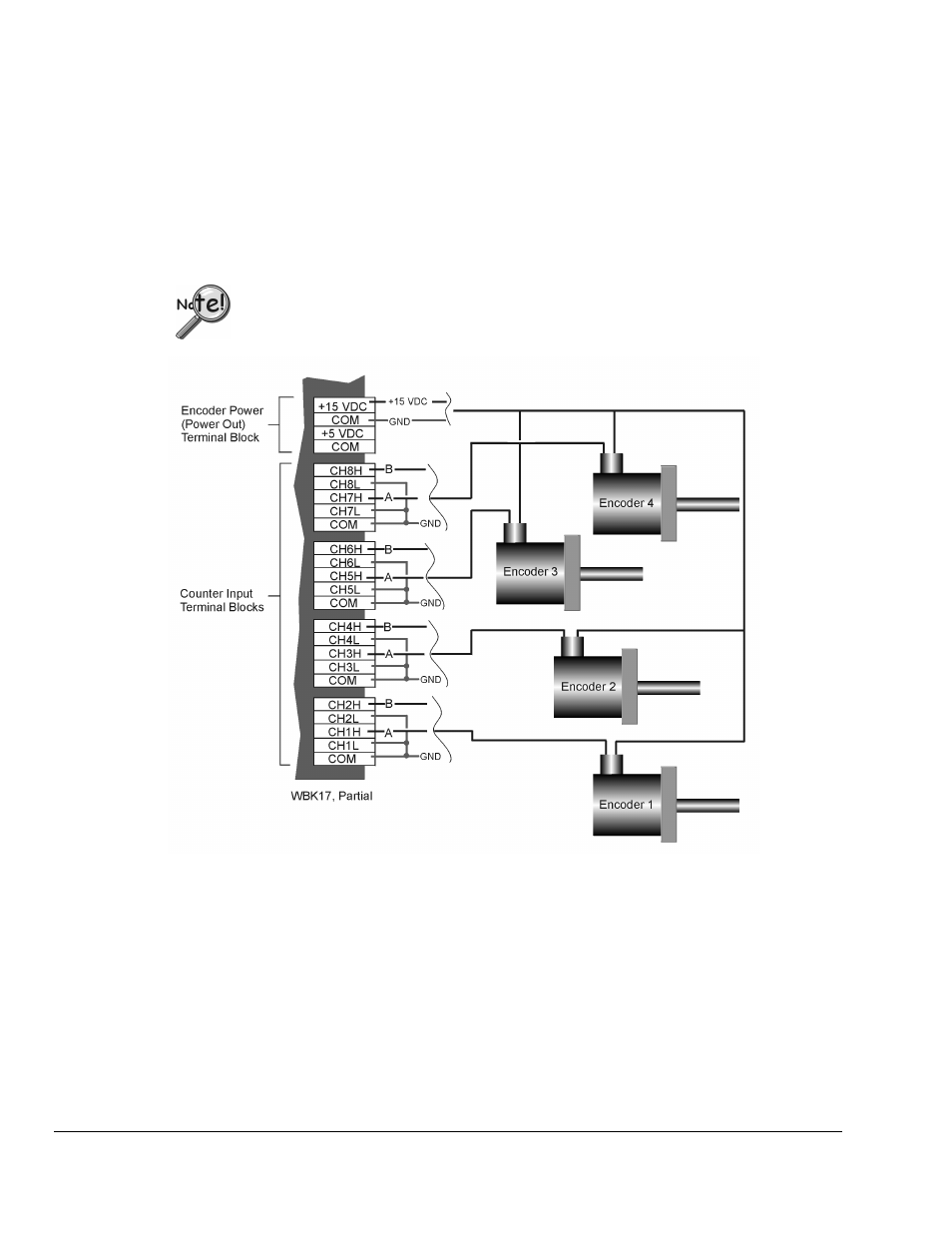
Wiring for 4 Encoders
The following figure illustrates single-ended connections for four encoders. For differential connections
we would simply make /A, /B, and /Z signal connections to the respective channel low inputs. With four
encoders it should be noted that there are no channels available for Z, /Z signals. In this scenario no
encoder has a Z signal connection.
The WBK17 can receive input from up to four encoders; however, the WaveView data
acquisition program can accept input from only one or two encoders. To receive input
from three or four encoders [with one WBK17] refer to the Programmer’s Manual
(p/n 1008-0901).
Four Encoders with Single-Ended Connections to WBK17
Connect four encoders to the WBK17. Refer to the above diagram and following table, Four Encoders –
Example Setup, as needed. Each signal (A, B) can be connected as a single-ended connection with respect
to the common ground or as a true differential input. All four encoders can draw their power from the
power output connector, connect the encoder’s power input to the +5V or +15V power, connect the return
to COM on the same connector. Make sure that the current output spec is not violated or a fuse may blow.
The programming setup given below is just a representative of possible options.