Encoder mode – Measurement Computing WBK17 User Manual
Page 20
WBK17, pg. 20
987996
WBK17, Counter/Encoder Module
TIMING: OPT2: This determines whether the time is to be measured with a 16-bit (Counter Low), or
32-bit (Counter High) counter. Since time measurements always have the “stop at the top” option enabled,
this option dictates whether the measurement has a range of 0 to 65535 ticks or 0 to 4,294,967,295 ticks.
Encoder Mode
Introduction
Rotary shaft encoders are frequently used with CNC equipment, metal-working machines, packaging
equipment, elevators, valve control systems, and in a multitude of other applications in which rotary shafts
are involved.
The encoder mode allows the WBK17 to make use of data from optical incremental quadrature encoders.
When in the encoder mode, the WBK17 accepts either differential or single-ended inputs and provides
power for up to four encoders. When reading phase A, phase B, and index Z signals, the WBK17 provides
positioning, direction, and velocity data.
The WBK17 can receive input from up to four encoders; however, the WaveView data
acquisition program can accept input from only one or two encoders. To receive input
from three or four encoders [with one WBK17] refer to the Programmer’s Manual
(p/n 1008-0901).
The WBK17 supports quadrature encoders with a 16-bit (Counter Low), or a 32-bit (Counter High) counter,
5 MHz frequency, and x1, x2, and x4 count modes. With only phase A and phase B signals, 4 channels are
supported; with phase A, phase B, and index Z signals, 2 channels are supported.
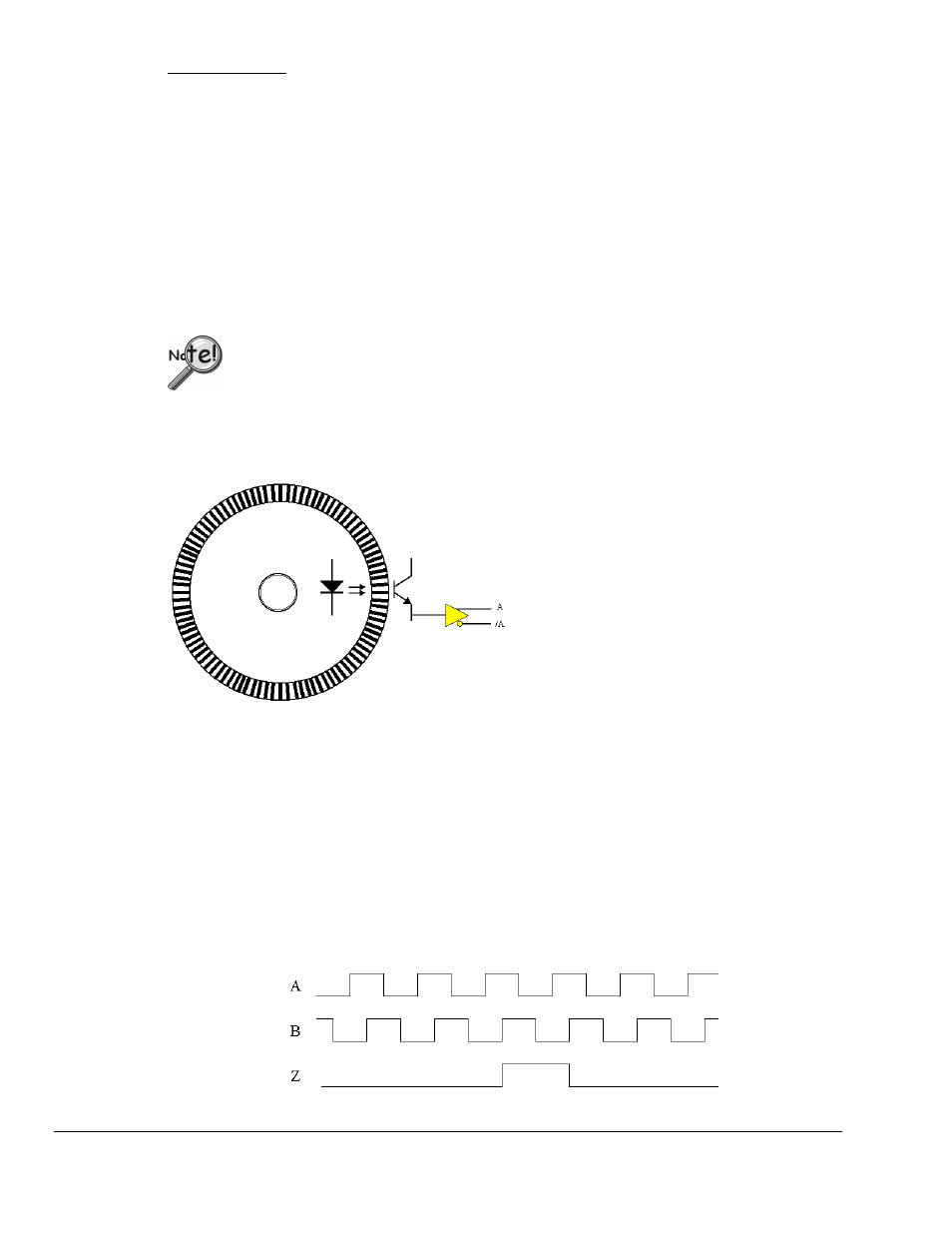
Quadrature encoders generally have 3 outputs: A, B, and Z. The A and B signals are pulse trains driven by
an optical sensor inside the encoder. As the encoder shaft rotates, a laminated optical shield rotates inside
the encoder. The shield has three concentric circular patterns of alternating opaque and transparent
windows through which an LED will shine. There is one LED for each of the concentric circular patterns
and likewise, one phototransistor. One phototransistor produces the A signal, another phototransistor
produces the B signal and the last phototransistor produces the Z signal. The concentric pattern for A has
512 window pairs (or 1024, 4096, etc.) The concentric pattern for B has the same number of window pairs
as A except that the entire pattern is rotated by 1/4 of a window-pair. Thus the B signal will always be
90 degrees out of phase from the A signal. The A and B signals will pulse 512 times (or 1024, 4096, etc.)
per complete rotation of the encoder.
The concentric pattern for the Z signal has only one transparent window and therefore pulses only once per
complete rotation. Representative signals are shown in the figure below.
Representation of Quadrature Encoder Outputs: A, B, and Z