Measurement Computing WBK17 User Manual
Page 21
WBK17, Counter/Encoder Module
987996
WBK17, pg. 21
As the encoder rotates, the A (or B) signal is indicative of the distance the encoder has traveled. The
frequency of A (or B) indicates the velocity of rotation of the encoder. If the Z signal is used to zero a
counter (that is clocked by A) then that counter will give the number of pulses the encoder has rotated from
its reference. The Z signal is a reference marker for the encoder. It should be noted that when the encoder
is rotating clockwise (as viewed from the back), A will lead B and when the encoder is rotating counter-
clockwise, A will lag B. If the counter direction control logic is such that the counter counts upward when
A leads B and counts downward when A lags B, then the counter will give direction control as well as
distance from the reference.
An Example of Encoder Accuracy
If there are 512 pulses on A, then the encoder position is accurate to within 360 degrees/512. Even greater
accuracy can be obtained by counting not only rising edges on A but also falling edges on A, giving
position accuracy to 360 degrees/1024. The ultimate accuracy is obtained by counting rising and falling
edges on A and on B (since B also has 512 pulses.) This gives a position accuracy of 360 degrees/2048.
These 3 different modes are known as 1X, 2X, and 4X. The WBK17 implements all of these modes and
functions, as described in the following options.
Encoder Mode
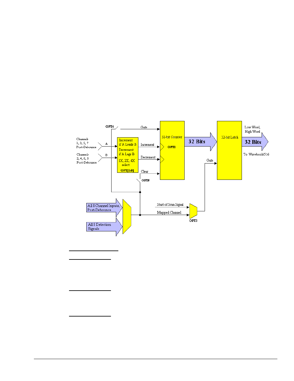
ENCODER: OPT[1:0]: This determines the encoder measurement mode: 1X, 2X, or 4X.
ENCODER: OPT3: This determines which signal latches the counter outputs into the data stream going
back to the WaveBook. Normally, the start of scan signal latches the counter outputs at the beginning of
every scan. The other option is to have the mapped signal latch the counter outputs. This allows the user to
have another signal control the latching of the count data, so the exact value of the counter is known when
an edge is present on another channel.
ENCODER: OPT4: This allows the mapped channel to gate the counter if desired. When the mapped
channel is high, the counter is enabled to count, when the mapped channel is low, the counter is disabled
(but holds the count value.) The mapped channel can be any other input channel or one of the detection
signals.
ENCODER: OPT5: This allows the mapped channel to clear the counter if desired. OPT5 implements
the Z-function [described above], allowing the encoder reference to clear the counter. The counter is
cleared on the rising edge of the mapped channel.