Digital inputs – Measurement Computing WBK17 User Manual
Page 29
WBK17, Counter/Encoder Module
987996
WBK17, pg. 29
Four Encoders – Example Setup
Channel
Connection
Programming Setup
1
Encoder1 – A
Encoder Mode, 1X option, 16-bit counter, Latch on SOS
2
Encoder1 – B
Period Mode, 1Xperiod option, 16-bit counter, Map channel doesn’t gate,
Ticksize to 20000ns
3
Encoder2 – A
Encoder Mode, 2X option, 16-bit counter, Latch on SOS
4
Encoder2 – B
Period Mode, 1Xperiod option, 16-bit counter, Map channel doesn’t gate,
Ticksize to 2000ns
5
Encoder3 – A
Encoder Mode, 4X option, 16-bit counter, Latch on SOS
6
Encoder3 – B
Period Mode, 1Xperiod option, 16-bit counter, Map channel doesn’t gate,
Ticksize to 200ns
7
Encoder4 – A
Encoder Mode, 4X option, 16-bit counter, Latch on SOS
8
Encoder4 – B
Period Mode, 1Xperiod option, 16-bit counter, Map channel doesn’t gate,
Ticksize to 200ns
With the encoders connected in this manner there is no relative positioning information available since there
is no Z signal connection. Therefore only distance traveled can be measured on the A channels. This
means that for each encoder we can only know distance traveled and velocity of travel.
Setpoints can be done just like in the previous example. The digital output port can be updated by any
individual channel, a set of selected channels, or by all channels.
Digital Inputs
The WBK17 has 16 general-purpose digital inputs that can be scanned into an acquisition along with any
other channel on the WaveBook system. These are available on the 25 pin DSUB connector [Digital
Inputs, Trigger, External Clock connector] located on the WBK17 front panel, as shown in the figure on
page 1 of this document module.
The following signals are present on the DB25F high-speed digital I/O connector.
• 16 High-Speed Digital Input Lines (D0 through D15)
• TTL Trigger Input (TTLTRG)
• +15 V (pin 23), -15 V (pin 22), 50 mA max. (each)
• two +5 V (pin 19 and pin 21), 250 mA max. (total)
• External Clock (pin 20)
• two Digital Grounds (pins 24 and 25)
To sample just 16 digital input signals, connect them directly to the digital Input data lines.
D15 is the most significant bit, and D0 is the least.
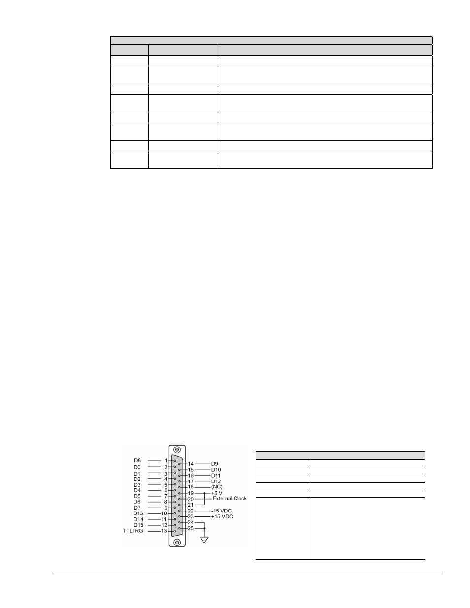
The following figure depicts WBK17’s DB25 connector, rotated 90 degrees counter-clockwise for
convenience of labeling. Note that an optional Clock and External Trigger cable (CA-178) is available for
use with the WBK17. The cable connects to the DB25 connector and terminates in two BNC connectors,
one for an external clock (via pin 20) and the other to TTL external trigger (via pin 13).
Digital I/O Connections for WBK17
D0 – D15
High Speed Digital Input data lines
TTLTRG
TTL trigger input
External Clock
16 bit mode, read/write strobe
+5 VDC
250 mA maximum
+15,-15 VDC
50 mA maximum (each)
WBK17’s DB25 Pinout
Digital Grounds
Pins 24 and 25