Timing mode – Measurement Computing WBK17 User Manual
Page 19
WBK17, Counter/Encoder Module
987996
WBK17, pg. 19
Timing Mode
This mode provides a means of measuring time between two subsequent events, i.e., the edge of one
channel with respect to the edge of another channel. The edge selection is done in each channel’s debounce
setup. Whenever the time measurement is latched from the counter, the counter is immediately cleared and
enabled for accepting the subsequent time period, which starts with the next edge on the main channel.
Timing Mode
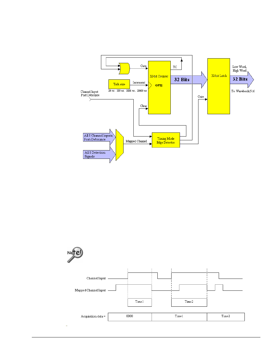
An Example of Timing Mode
The following example represents one channel in timing mode. The time desired is between the rising edge
on the input channel and the falling edge on the mapped channel. Zeroes are returned, in the scan, until
one complete time measurement has been taken. At that point, the value (time in ticks) is latched and
output to the WaveBook until the next time measurement has been completed. Rising edges on the input
channel will clear the counter and falling edges on the mapped channel will latch the output of the counter
at that time. If the scan period is much slower than the rate of time-frames coming [available on the two
channels] then the data will miss some time-frames. The scan period can be decreased to capture more
time-frames.
The data returned is interpreted as time measured in ticks. This data represents the number of ticksize
intervals counted during the timing measurement. There are four timebase settings: 20 ns, 200 ns, 2 µs, and
20 µs. These are often referred to as tick-sizes. The WBK17 uses a 50 MHz, 10 ppm oscillator as a timing
source.
If the input signal has a poor slew rate the timing mode will provide variant results,
dependant upon the comparator threshold.
Example of One Channel in Timing Mode