3 model code – K-Patents PR-03 User Manual
Page 98
98
98
98
98
92
PR-03 instruction manual
1.
Important:
Before you upgrade any program versions, write down all
current parameters from the calibration screen of the Indicating trans-
mitter. Also remember to take note of the wash and relay parameters.
2. Power off and open the front panel of the IT-R.
3. Unscrew the cover on the inside of the front panel. Unplug the cable
from the Power supply card to the front panel and remove the cover to
see the Processor card.
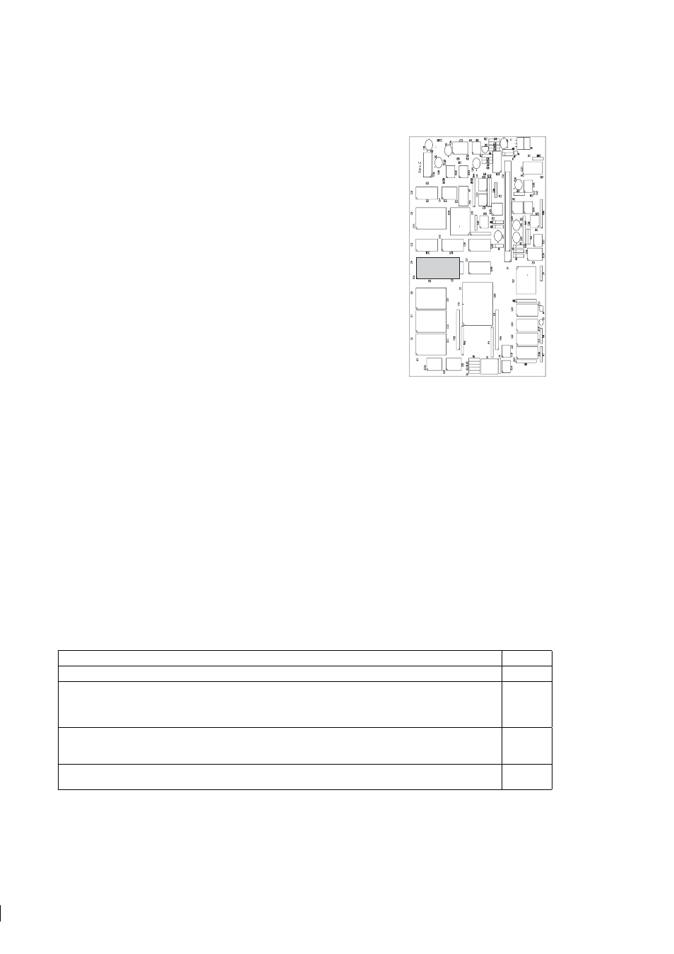
4. Carefully remove the old EPROM (Figure 9.3)and insert the new one.
5. Place the cover over the Processor card, screw it on and reconnect the
cable from the Power supply card to the front panel. Close the front
panel.
6. Press the ENTER button and at the same time switch on the power. You
will now enter the Factory Calibration mode.
7. Press 1 for Default settings. Make sure that all pre-upgrade parameters
have been written down.
EPROM
Figure 9.3
Location
of the EPROM on
the Processor card
8. Press ENTER to load default parameters and press RESET twice to exit from the Factory calibration.
9. Switch power off. Switch power back on.
10. Enter all the pre-upgrade parameters (wash and relay parameters included) into the transmitter.
Note:
The image inversion needed with the Probe refractometer PR-03-P sensor was first implemented in
the main program version 8.6. Program version 8.5 can be updated to manage the image inversion. Versions
below 8.5 are not compatible with the Probe refractometer PR-03-P sensor.
9.3 Model code
9.3.1 IT-R model code
MODEL AND DESCRIPTION
MODEL
IT-R = Indicating Transmitter
IT-R
Cable connection
U = 1/2 inch NPT-type conduit hubs
U
E = BF11/PG11 cable glands (with -GP option only)
E
M = M20x1.5 metric cable glands (with -GP option only)
M
Electrical classification
-GP = General purpose
-GP
-CS = CSA appr. for use in general purpose (ordinary) locations
-CS
Transmitter options
-WR = Relay unit, 2 relays
-WR