K-Patents PR-03 User Manual
Page 60
60
60
60
60
54
PR-03 instruction manual
6.4.3 Assembling the probe sensor
1. Fit the core module into the sensor head. Note the alignment pin (R), Fig-
ure 6.5.
2. Mount the thermal conductor (K) with the holes aligned to the screw holes.
Mount the disk spring (J). Note the position of the disk spring on the detail
(J), Figure 6.5.
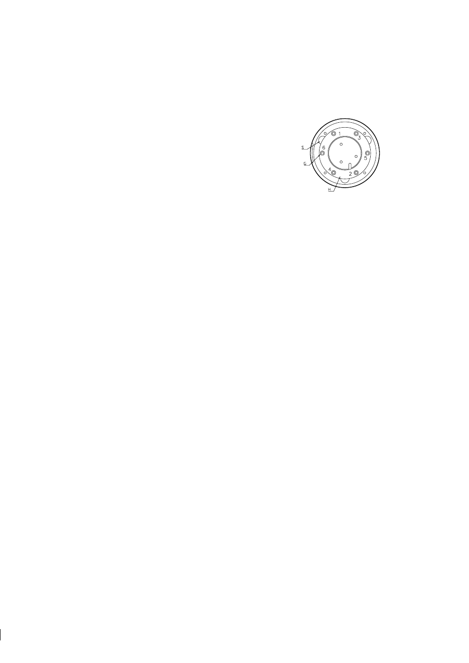
3. Mount the disk spring holder (H). Fasten the six screws (G) in small steps
following the pattern of numbers in Figure 6.8. Continue until the holder
surface is flush with the surfaces of the three notches (S). No step should be
felt with the finger tip.
Figure 6.8
Tightening the
spring holder screws
4. Mount the Image detector card with the screws (F), Figure 6.5. First tighten the two guiding screws with
conical heads, then the third screw. Lock the screws with e.g. nail polish.
5. Mount the Image digitizer card with the screws (E). Connect (B), (C) and (D).
6. Check the dryer color, Figure 6.1. It should be yellow. If it is green, replace the dryer.
7. Place the sensor on a table with the prism upwards. Use a sharp knife with a curved edge to cut away
the circular piece of the gasket covering the prism.
Warning!
Support the knife on the prism surface
!
only as it will scratch the steel. Now the sensor is ready for process installation. Remember to check the
calibration (Section 5.10.1, “Checking current calibration”, and Appendix D, “Instrument verification
ISO 9000”).