4 disassembling and assembling a probe sensor – K-Patents PR-03 User Manual
Page 57
57
57
57
57
6 Regular maintenance
51
6. Check the dryer color, Figure 6.1. It should be yellow. If it is green, replace the dryer.
7. Connect (A), close the sensor cover and mount the Vee-clamp. The nut and bolt of the clamp should be
on the same side as the cable connector.
8. Place the sensor on a table with the prism upwards. Use a sharp knife with a curved edge to cut away
the circular piece of the gasket covering the prism.
Important:
Support the knife on the prism surface
only as it will scratch the steel.
9. Now the sensor is ready for process installation. Remember to check calibration (Section 5.10.1, “Check-
ing current calibration” and Appendix D, “Instrument verification ISO 9000”).
6.4 Disassembling and assembling a probe sensor
Warning!
Always check that the pipeline or the vessel is empty before removing a sensor from the process
!
line. Never remove the sensor if there is process liquid in the pipe or the vessel.
6.4.1 Disassembling the probe sensor
1. Disconnect the cable. Apply the two connector protection caps. Remove the sensor from the process,
and rinse.
Warning!
Wear appropriate protective clothing and be very careful when removing the sensor from the
!
process line!
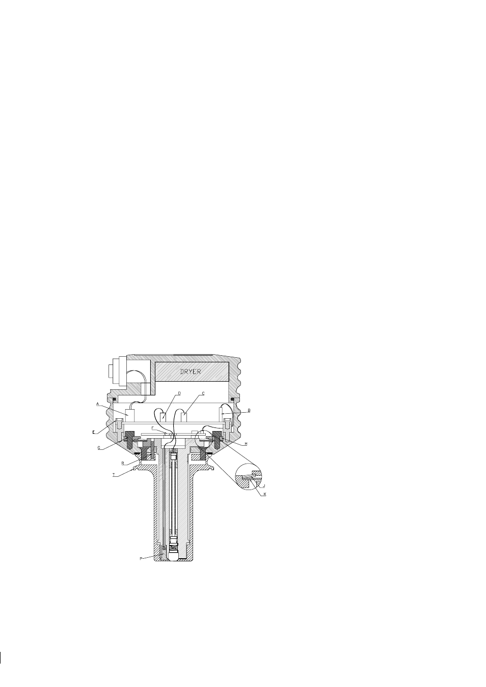
Figure 6.5
Probe sensor in disassembly position
2. Fix the sensor by the sensor head (T) in a ver-
tical position, sensor label upwards, Figure 6.5.
K-Patents Service stand PR-1002 can be used.
3. Remove the nut of the Vee-clamp. Move the
Vee-clamp one step downwards.
4. Lift the sensor cover and disconnect the cable
(A) from the image digitizer card.
5. Disconnect the ribbon cable (B), the LED lead
(C), and the temperature element lead (D).
6. Remove the Image digitizer card kept by four
M4 screws (E).
7. Remove the Image detector card kept by three
M3 screws (F).
Note:
Removing the screws may introduce a
slight calibration error.