Ab c d – K-Patents PR-03 User Manual
Page 40
40
40
40
40
34
PR-03 instruction manual
5.5 Soft key Calibrate: Viewing and changing system settings
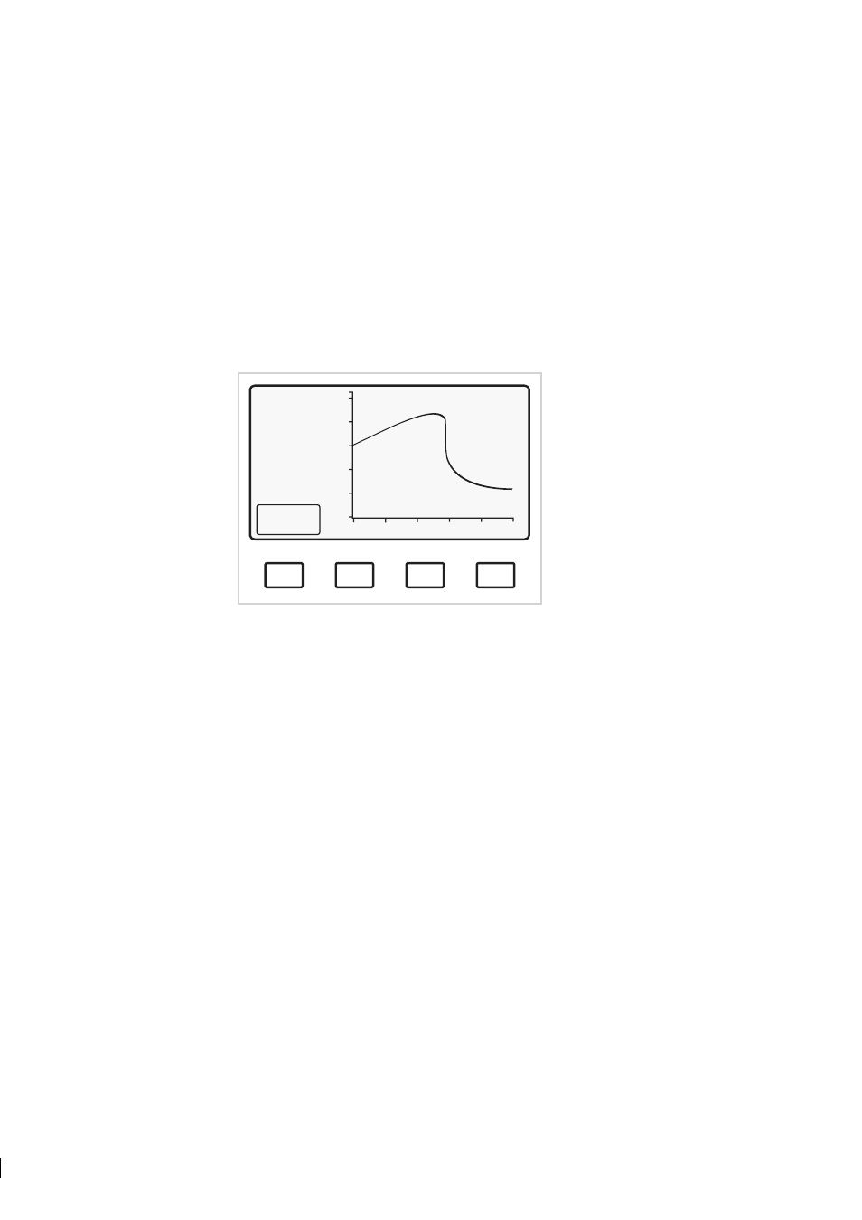
5.5.1 Viewing Optical image and raw data
It is possible to view all raw data from the sensor including the optical image followed by the Scaled
Image
, Slope and Image Diagnostics displays (see the selection tree, figure 9.5). Starting from the Normal
display, select Calibrate/Optical image to get the complete optical image. The display (Figure 5.7)
contains now all raw data from the Sensor including the signals from each photo cell, i.e. the raw video
signal. This differs from the Optical image, Figure 5.6, selected through the Display key.
A
B
C
D
RAW
SENSOR
DATA
RMN: 2
RMX: 216
LED: 96
Scans: 2
A/D: 314
Sts: 00h
HT: 143
HH: 10
Scaled
image
Normal operation
Figure 5.7
Complete optical image with raw data
For information on the diagnostic messages shown on this screen, see Section 9.7.
5.5.2 Raw data explanations
RMN, RMX
Minimum and maximum of the raw video signal. This signal is calculated on the Processor
card from the video signal. The scale is 0-255, corresponding to full scale on display. The
light intensity is controlled to keep RMX in the range 170-190.
LED
The LED exposure control signal on a light intensity scale 1-255. The flashing red light of
the LED can be seen directly. If the operation is correct, the displayed LED value should be
above 20 and below 200.
Scans
Number of optical images during one calculation cycle, typically 1 or 2. The scan pulses
(with 5 V amplitude) can be measured at TP 3
A/D
This refers to the temperature measurement
Sts
Sensor status bits determined by the type of Image Detector card: "04h" indicates a Process
refractometer PR-03. One bit added, "05h", indicates DETECTOR TIMEOUT.