K-Patents PR-03 User Manual
Page 59
59
59
59
59
6 Regular maintenance
53
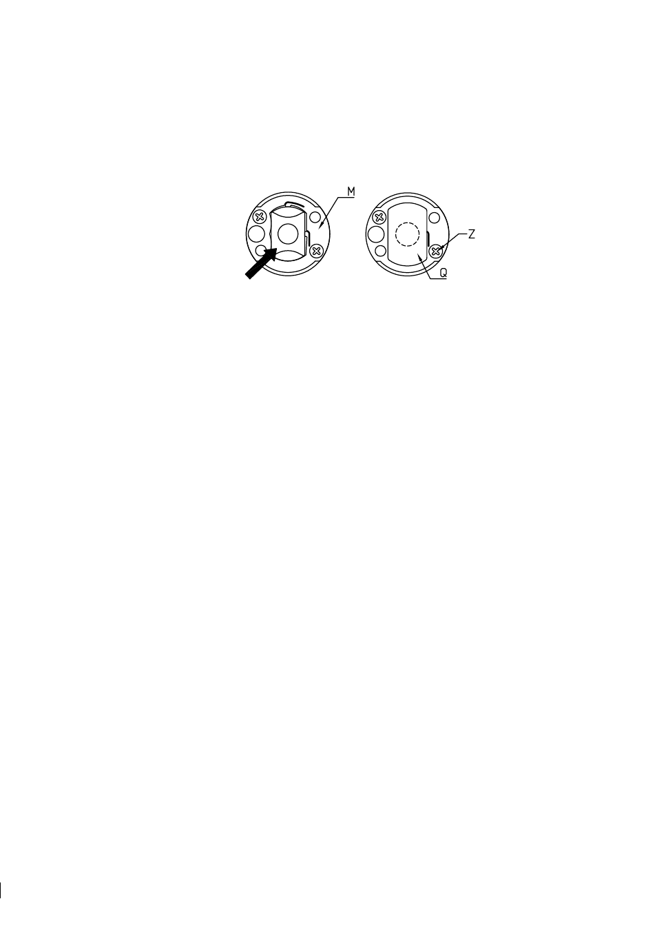
12. Put the prism in place pushing gently against the springs of the prism plate (M). The direction of the
force is indicated by an arrow in Figure 6.7 (a). To make sure the prism is in correct position, press the
prism in the opposite direction of the arrow.
(a)
(b)
Figure 6.7
The prism plate, the prism and prism gaskets
13. Put the prism support (U) upon the gasket. Keep the gasket in place with a fingertip in the middle.
Check that the gasket is symmetrical around the middle of the prism surface. Tighten the screws with
hemispherical heads (L) to the bottom, Figure 6.6 (b).
14. Push the temperature sensor (P) into its proper position. Mount the LED plate (Y). Check that the
temperature sensor (P) is properly springloaded. In outer position, the sensor tip is level with the prism
surface, Figure 6.6 (b). It should flex inwards 2-3 mm as indicated by an arrow, but return to the outer
position.
15. Now the CORE module is assembled. It should be checked before mounting into the sensor head:
a. Clean the window of the CCD-element (V), Figure 6.71 (a). Attach the Image detector card to the
Analyzer module by the two screws (F) with conical heads. Connect electrically all cards, with
connectors (A), (B), (C), and (D).
b. Connect the indicating transmitter, and inspect the optical image on Raw sensor data display, key
sequence Calibrate / Optical image.
c. The optical image must form a smooth curve. Dips or separate single points indicate that the optical
surfaces (e.g. the CCD window) are not clean.
Important:
The prism must be covered to exclude
external light.
d. When the image is OK, switch power off and disconnect all cards. Dismount the Image detector
card from the CORE module.
16. The Core module is now ready for sensor assembly.