K-Patents PR-03 User Manual
Page 25
25
25
25
25
4 Accessory units
19
A
B
C
D
44
46
48
50
45
47
49
51
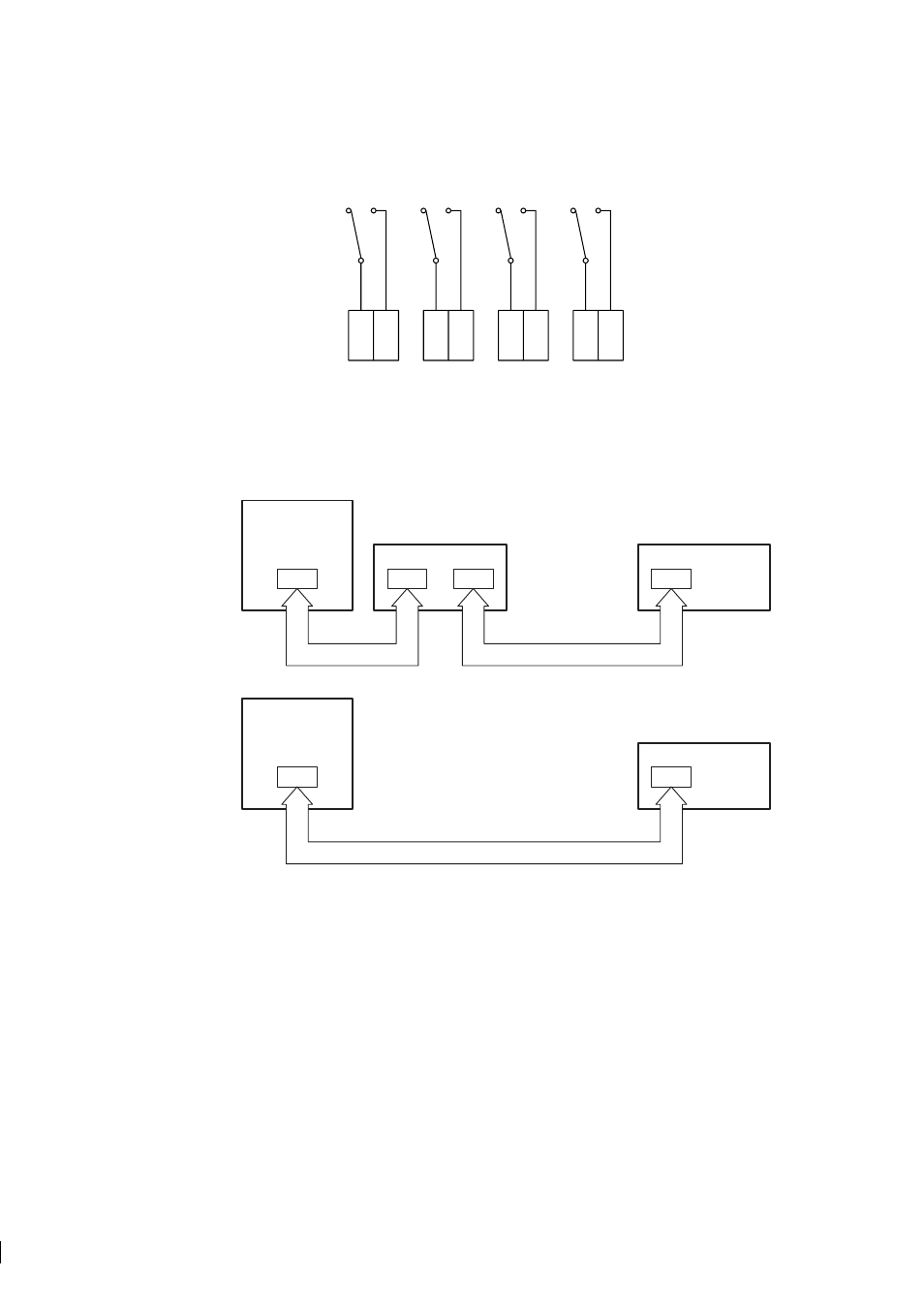
Figure 4.2
Relay unit PR-7080 connector strip
Connect the numbered leads of the interconnecting cable with the same numbers (8-14) on the serial bus.
Then proceed to connect the cable with your refractometer system. If you have an External output unit, the
Relay unit is connected to that. If no other external units are used, the Relay unit connects directly with the
IT-R (Figure 4.3).
Indicating
transmitter
Indicating
transmitter
8-14
8-14
8-14
8-14
8-14
8-14
A
B
External output unit
Relay unit
Relay unit
PR-8011
PR-8011
PR-8011
Figure 4.3
Connecting Relay unit PR-7080
Important:
Before connecting the relay unit with your refractometer system, power off your system. If you
have an external output unit, open its cover to access the card inside for connections. If you don’t have an
external output unit, open the IT-R’s enclosure and display panel to access the processor card.
Connect the numbered leads of the free cable end with terminals with the same numbers (8-14) on the
serial bus output (serial bus B) on the Output unit card or on the serial bus on the Indicating transmitter’s
processor card.