K-Patents PR-03 User Manual
Page 17
17
17
17
17
3 Indicating transmitter (IT-R)
11
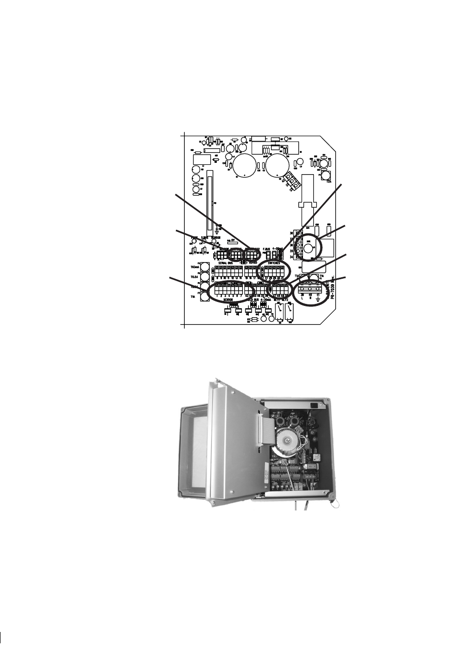
3.2.2 Electrical connections
All the electric terminals of the Indicating transmitter are on the Power supply card (Figure 3.5).
11
POWER
SELECTOR
POWER
CONNECTION
SERIAL CABLE
(pc)
SENSOR
CABLE
ACCESSORY UNIT
(serial bus)
SWITCHES
RELAYS
Figure 3.5
Power supply card layout
To access the Power supply card, first open the enclosure cover. Then loosen the two screws on the right-
hand corners of the front panel and swing open the front panel to see the card.
Figure 3.6
IT-R with opened front panel.