K-Patents PR-23-SD Generation 1 User Manual
Page 27
Safe-Drive™ Process Refractometer PR-23-SD Best Practices, Generation 1
© Copyright K-Patents 2013. All rights reserved.
27
4. Connect the primary AC power to a separate terminal strip in the lower right-hand
corner of the motherboard. The three terminals are marked 31/L, 32/N, and 33/
PE (protective earth), which is directly connected to the exposed metal parts if
the transmitter.
5. Connect the wiring wash relay to solenoid valve from the RELAYS terminals.
6. Connect the 4-20mA output.
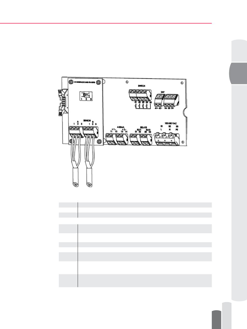
Figure 15
Transmitter H1 and motherboard connections
H1
A 1 2 3
Connection for Sensor A, signal wires (1, 2), cable shield (3).
B 1 2 3
Connection for Sensor B, signal wires (1, 2), cable shield (3).
Motherboard
11 12
4–20 mA output 1, positive (11), negative (12), max. load 1000 Ohm, galvanically
isolated.
13 14
4–20 mA output 2, positive (13), negative (14), max. load 1000 Ohm, galvanically
isolated.
21 22
Relay 1, one contact output, max. 250 V AC, max. 3 A.
23 24
Relay 2, one contact output, max. 250 V AC, max. 3 A.
31 32 33
Power, L (31), N (32), protective earth (33), 100-240 V AC, 50–60 Hz. An external
power switch is recommended.
41 42
24V terminal for DTR internal use only.
NOTE: Connecting terminal to external 24V supply will void warranty. Connecting
external devices to 24V terminal will void warranty.
51 52 53
54 55
Switch inputs: switch 1 (51), switch 2 (52), switch 3 (53), switch 4 (54) and common
(55). A voltage of 3 V DC is provided over each switch.
The switch terminals are galvanically isolated.