Hypertherm MicroEDGE Pro Shape Cutting Control Rev.2 User Manual
Page 122
Maintenance and diagnostics
4-26
MicroEDGE Pro
Instruction Manual 807290
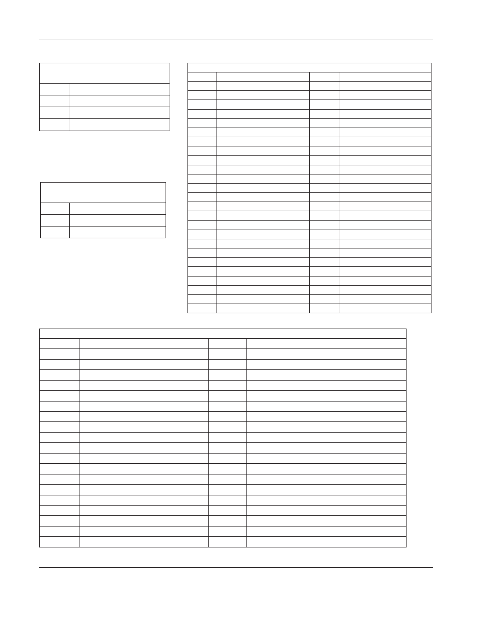
Connector j4 (I/o 19–24), j5 (I/o 13–18), j6 (I/o 7–12), j7 (I/o 1–6)
Pin no.
Signal
Pin no.
Signal
1
+24 V Field
20
Output 19A, 13A, 7A, 1A
2
Input 19, 13, 7, 1
21
Output 19B, 13B, 7B, 1B
3
Common
22
+24V Field
4
+24 V Field
23
Output 20A, 14A, 8A, 2A
5
Input 20, 14, 8, 2
24
Output 20B, 14B, 8B, 2B
6
Common
25
+24 V Field
7
+24 V Field
26
Output 21A, 15A, 9A, 3A
8
Input 21, 15, 9, 3
27
Output 21B, 15B, 9B, 3B
9
Common
28
+24 V Field
10
+24 V Field
29
Output 22A, 16A, 10A, 4A
11
Input 22, 16, 10, 4
30
Output 22B, 16B, 10B, 4B
12
Common
31
+24 V Field
13
+24 V Field
32
Output 23A, 17A, 11A, 5A
14
Input 23, 17, 11, 5
33
Output 23B, 17B, 11B, 5B
15
Common
34
+24 V Field
16
+24 V Field
35
Output 24A, 18A, 12A, 6A
17
Input 24, 18, 12, 6
36
Output 24B, 18B, 12B, 6B
18
Common
37
Shield
19
+24 V Field
Connector j3 (to and from MCC and serial isolation board)
Pin no. Signal
Pin no. Signal
1
Input 1
26
Output 13
2
Output 1
27
Input 14
3
Input 2
28
Output 14
4
Output 2
29
Input 15
5
Input 3
30
Output 15
6
Output 3
31
Input 16
7
Input 4
32
Output 16
8
Output 4
33
Input 17
9
Input 5
34
Output 17
10
Output 5
35
Input 18
11
Input 6
36
Output 18
12
Output 6
37
Input 19
13
Input 7
38
Output 19
14
Output 7
39
Input 20
15
Input 8
40
Output 20
16
Output 8
41
Input 21
17
Input 9
42
Output 21
18
Output 9
43
Input 22
19
Input 10
44
Output 22
20
Output 10
45
Input 23
21
Input 11
46
Output 23
22
Output 11
47
Input 24
23
Input 12
48
Output 24
24
Output 12
49
Ground
25
Input 13
50
Ground
Connector j2
(from power distribution board)
Pin no. Signal
1
Ground
2
+5 V
Connector j1
(from power distribution board)
Pin no. Signal
1
+24 V
2
Field ground
3
+5 V