Dampers supported directly from structure (cont.) – Greenheck Ceiling Radiation Dampers (826252) User Manual
Page 9
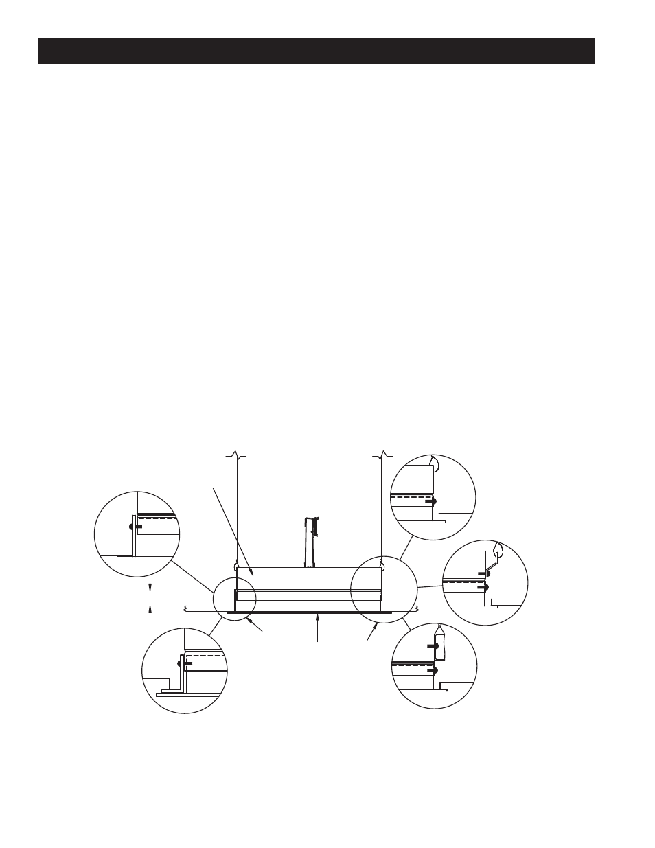
ALL HANGER WIRES
MUST BE VERTICAL
(NOT SPLAYED)!
3 3/4 in. Max.
Ceiling Radiation
Damper
DETAIL
D
Air
(Inlet or Outlet)
Device
Non-Ferrous
Device
DETAIL
C
DETAIL
B
DETAIL
A
Ferrous
Device
DETAIL
E
Figure 9
Dampers Supported Directly From Structure (cont.)
Unducted Surface Mounted Air Inlet Or Outlet Devices
t.BYJNVNTJ[FPGQFSNJUUFEPQFOJOHFRVBMTNBYJNVN
size of available listed ceiling radiation dampers.
t Opening in ceiling membrane may be up to one inch
larger than the nominal size of the ceiling radiation
damper (i.e. a 12 in. x 12 in. (nominal) ceiling radiation
damper could have a maximum ceiling membrane
opening of 13 in. x 13 in.).
t Connection of ceiling radiation damper and air device
neck (See Page 1, Paragraph 4) may be satisfied in
three ways:
1.
Ceiling radiation damper may be connected
directly to the air device neck and supported
by steel channel (See Detail A, Figure 9).
2.
Ceiling radiation damper may be connected
directly to the air device neck and supported
by hanger straps (See Detail B, Figure 9).
3.
Ceiling radiation damper may be connected
directly to the air device neck and supported
by direct suspension with wires looped
through holes in the damper frame before tying
(See Detail C, Figure 9).
Non-Ferrous Air Devices - Air devices that have
non-ferrous frames.
Ceiling membrane openings that utilize non-ferrous
devices require one of the following:
1.
A steel extension should extend from the
ceiling radiation damper to the bottom surface
of the ceiling membrane and the opening in
the ceiling membrane (see page 1, paragraph
3) should be equal to the outside of the steel
extension (see Detail D, Figure 9).
2.
A steel angle should be attached to the
bottom of the ceiling radiation damper and
span the gap from the ceiling radiation
damper to the bottom of the ceiling
membrane. The steel angle should overlap the
ceiling membrane (see Detail E, Figure 9).
Models CRD-1, CRD-1LP, CRD-2, and CRD-60 may
be installed as shown in Figure 9 (Model CRD-1
CRD-1LP Illustrated).
8