Installation, Installation guidelines – Greenheck Ceiling Radiation Dampers (826252) User Manual
Page 18
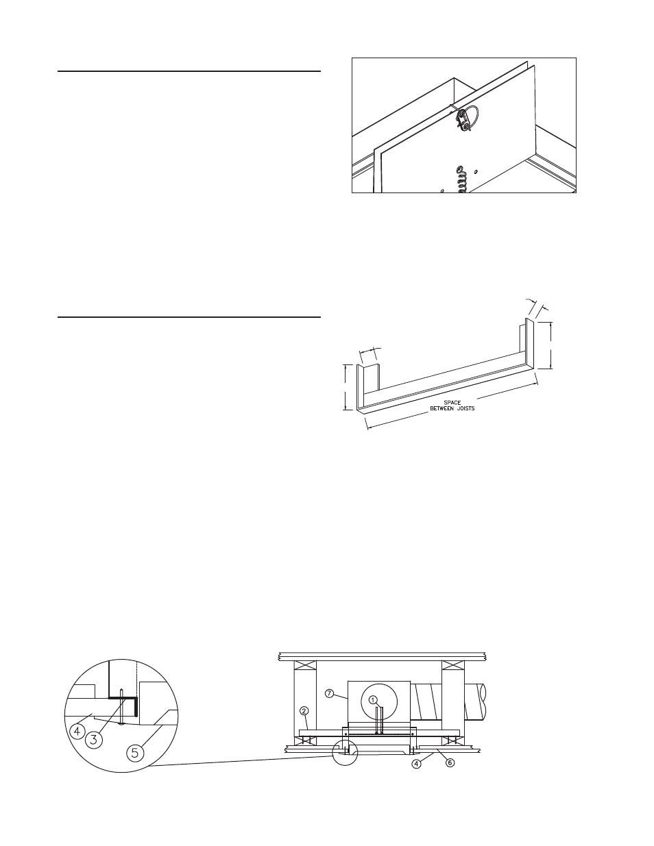
1) CRD’s are shipped from the factory with the blades in
the closed position. The fusible link must be installed
at the time of installation such that the blades are held
open as shown in Figure 2.
2) Fasteners (screws, bolts, rivet, etc.) used for installation
must not interfere with blade operation.
3) Flexible duct must be Class I or 0 type, bearing the
UL listed mark. Steel duct must be a minimum 28 ga.
(.5mm) and maximum 20 ga. (1mm).
4) Ceiling damper must be installed as described in these
installations.
5) Ceiling penetration shall be located between floor/
ceiling trusses.
6) Dampers supplied without a factory supplied plenum
box require a steel or ductboard plenum to be field
installed (see pages 4 and 5).
7) Dampers shipped with factory attached plenums MUST
be installed prior to sheetrock ceiling installation.
Installation
1) The damper assembly is to be attached to the trusses
using 2 - 1 in. x 1 in. x 16 ga. (25mm x 25mm x 1.5mm)
or 2 - 1 1/4 in. x 1 in. x 20 ga. (32mm x 25mm x 1mm)
mounting angles. See Figure 3 for alternate mounting
angle detail. Attach each mounting angles to the
damper with a minimum of 2 - #8 screws or 5/32 in.
(4mm) diameter steel rivets.
Note: Make sure the fasteners do not interfere with the
damper operation.
2) Install the damper assembly, with attached mounting
angles, between the trusses as shown in Figures 4 - 7
and attach mounting angles to the trusses using 4 - 1¼
in. long steel screws per mounting angle.
3) For grille mount installations, the grille/diffuser frame
shall be steel. The grille/diffuser shall be attached with
a minimum of 4 - 1 in. (25mm) long #6 screws run
through the gypsum wall board into the plaster flange
(Figure 4 and 5).
4) For duct mount installations, 1 in. x 1 in. x 24 ga.
(25mm x 25mm x 0.7mm) retaining angles shall be
installed on all four sides and shall be attached with a
minimum 4 - 1 in. (25mm) long #6 screws run through
the gypsum wallboard into the plaster flange (Figure 6
and 7).
Installation Guidelines
Figure 2
1/2 in.
mini
mum
3 in.
3 in.
1 in.
Figure 3 - Alternate Mounting Angle
(provided by others)
1. Damper
2. Mounting Angle
3. Plaster Flange
4. Gypsum Board
5. Grille
6. RC Channel
7. Steel Plenum
Figure 4: Grille Mount with Steel Plenum
Note: For grille mount installations, the damper blades shall be
maximum 3 1/4 in. (83mm) above the top of the ceiling plane. For
duct mount installations, the damper blades shall be maximum 1/8 in.
(6mm) above the top of the ceiling plane.