Field installation of steel plenums – Greenheck Ceiling Radiation Dampers (826252) User Manual
Page 19
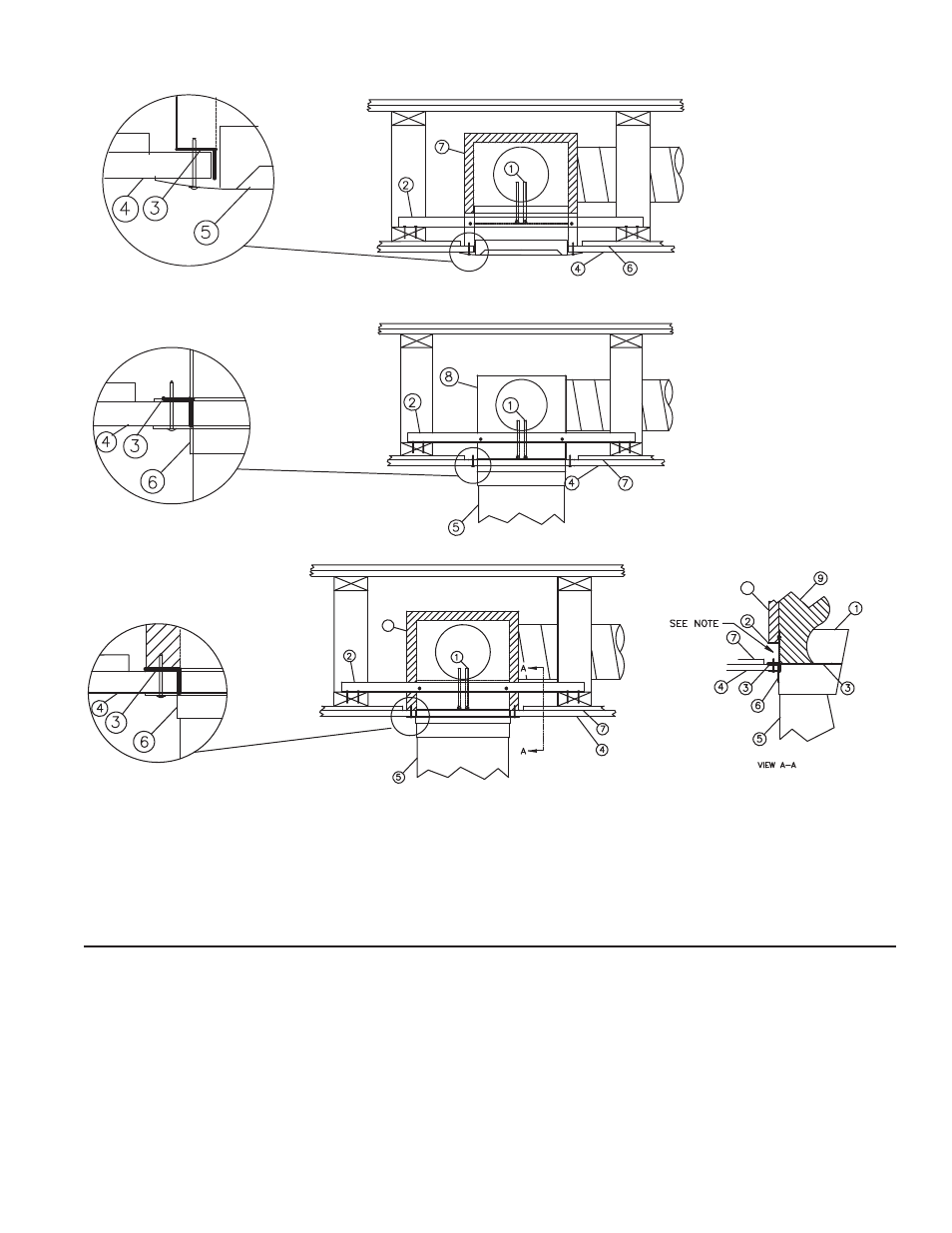
1. Damper
2. Mounting Angle
3. Plaster Flange
4. Gypsum Board
5. Grille
6. RC Channel
7. Duct Board Plenum
Figure 5: Grille Mount with Duct Board Plenum
1. Damper
2. Mounting Angle
3. Plaster Flange
4. Gypsum Board
5. Duct
6. Duct Retaining Angle
7. RC Channel
8. Steel Plenum
Figure 6: Duct Mount with Steel Plenum
1. Damper
2. Mounting Angle
3. Plaster Flange
4. Gypsum Board
5. Duct
6. Duct Retaining Angle
7. RC Channel
8. Duct Board Plenum
Note: Trim duct board to install mounting
angle. It is not necessary to re-install
trimmed piece to maintain UL certification.
8
8
Figure 7: Duct Mount with Duct Board Plenum
Field Installation of Steel Plenums
1.
The steel plenum box shall be a minimum of 28 ga.
(0.47mm) of galvanized steel.
2.
The inside width x length dimensions of the steel
plenum shall be sized no greater than 1/8 in. (3mm)
larger than the damper frame. The maximum plenum
height shall be 14 in. (356mm) as illustrated below.
The plenum should be sized to provide a snug fit
over the damper frame.
3.
The plenum duct collars shall be a minimum of 30
ga. (.39mm) galvanized steel. The total area of the
plenum box duct collars shall not exceed 78.5 sq. in.
(1994 sq. mm) with a maximum of two duct collars
per plenum. Duct collars shall be securely fastened
to the plenum surface. Any segment of the duct
collar that protrudes inside the plenum wall must not
interfere with the damper blade operation.
4.
The steel plenum box is to be attached to the
damper using a #8 screws, 1/8 in. (3mm) rivets,
spot welds or tack welds. Minimum of two per side
(Figure 8).
5.
The attachment of the screws or rivets must not
interfere with damper operation.