Installation guidelines, Installation – Greenheck Ceiling Radiation Dampers (826252) User Manual
Page 15
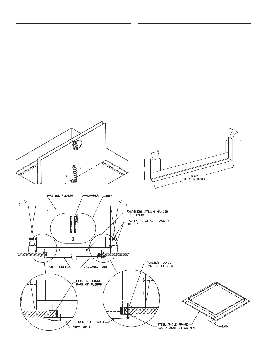
Installation Guidelines
1) CRD’s are shipped from the factory with the blades
in the closed position. The fusible link must be
installed at the time of installation such that the
blades are held open as shown in Figure 2.
2) Fasteners (screws, bolts, rivet, etc.) used for
installation must not interfere with blade operation.
3) Flexible duct must be Class I or 0 type, bearing the
UL listed mark. Steel duct must be a minimum 28
ga. (.5mm) and maximum 20 ga. (1mm).
4) Ceiling damper must be installed as described in
these installations.
5) Ceiling penetration shall be located between floor/
ceiling joists.
Figure 2
1/2 in.
mini
mum
3 in.
3 in.
1 in.
Figure 3
Figure 4
Installation
The damper assembly is to be attached to the joists
using 2 - 1 in. x ½ in. x 20 ga. (25mm x 13mm x 1mm)
mounting angles. See Figure 3.
1) Attach the mounting angles to the damper box on
the sides of the box without the supplied flanges.
Attach the mounting angles 5/8 in. (16mm) above the
bottom of the box (i.e. even with the flanges) using
minimum #8 sheet metal screws or 3/16 in. (4.5mm)
dia. steel rivets. Minimum 2 fasteners per angle and a
maximum of 2 in. (51mm) from the corner of the box.
2) Insert the damper assembly, with attached mounting
angles, between ceiling joists and attach to joists
using minimum 2 - #8 x ¾ in. (19mm) nails per side -
see Figure 4 and 5.