Dampers supported by a ceiling grid system, Ceiling radiation damper application cont, Lay-in diffuser applications – Greenheck Ceiling Radiation Dampers (826252) User Manual
Page 3
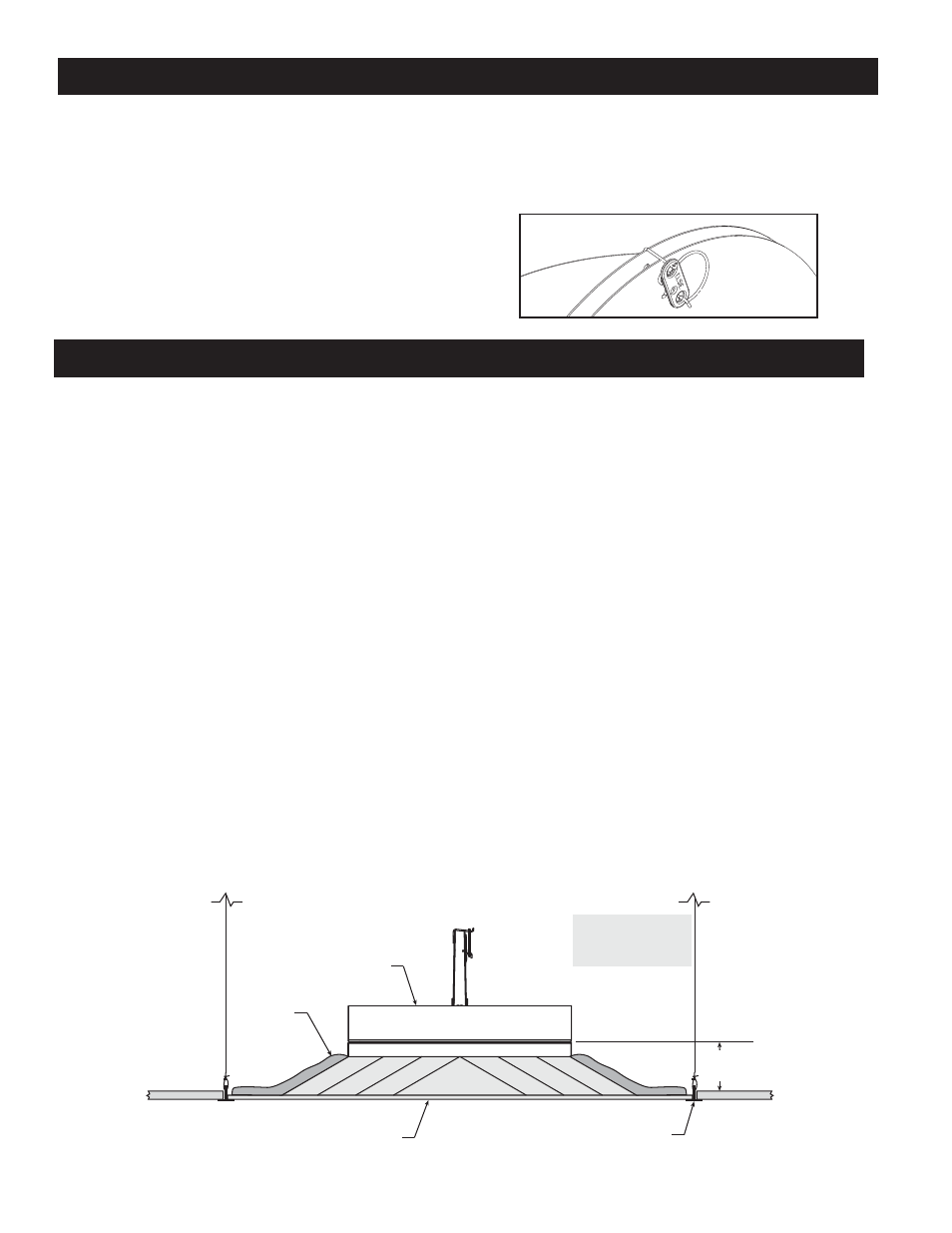
Lay-In Diffuser
t -BZJOEJGGVTFSJOTUBMMTEJSFDUMZJOUPFYQPTFE5FFCBS
grid system.
t $FJMJOHEBNQFSBUUBDIFTUPEJGGVTFSOFDL 4FF1BHF
1, Paragraph 4).
t 5IFSNBM#MBOLFUSFRVJSFE 4FF1BHF 1BSBHSBQI
5).
t *GGMFYJCMFEVDUJTVTFE 4FF1BHF 1BSBHSBQI
it shall be fastened to the diffuser neck with a steel
clamp or #16 SWG minimum wire.
Thermal
Blanket
Lay-In Diffuser
Ceiling Radiation
Damper
Tee Bar
All hanger wires
must be vertical
(not splayed)!
3 3/4 in.
Maximum
Figure 1
Dampers Supported By A Ceiling Grid System
Exposed Tee Bar ceiling grid systems often use “Lay
In” style air inlets and outlets. With attention to the
following requirements, the ceiling grid system provides
all required support for installation of “Lay In” style
ceiling dampers and air inlets and/or outlets.
Ceiling openings up to a 24 in. x 24 in. (576 in.
2
)
maximum are allowable. Maximum size limits of each
individual ceiling damper model must be observed.
The four corners of the grid module containing the air
device (or the midpoint of the adjacent cross-tees) shall
be directly supported from the structural members of
the floor or roof by 12 SWG minimum vertical hanger
wires. When the duct extends over the intersections of
the grid members, 16 ga. x 1
½
in. steel channels with
9/16 in. minimum flanges shall be used to ensure that
the grid is supported from structural members by 12
SWG minimum hanger wires. All UL Classified ceiling
assemblies require lay-in ceiling panels be cut to fill the
remainder of hole openings larger than 24 in. x 24 in.
and shall provide a minimum of 3/8 in. bearing on the
ceiling grid members.
Ceiling Radiation Damper Application Cont.....
5.
Thermal Blanket: In those installations where the
opening in the ceiling membrane is larger than the
ceiling damper (more than 1 in. in any dimension), a
Thermal Insulating Blanket (Model TB or QB) must
be installed by laying over the exposed surface of
the air inlet or outlet device. The Thermal Blanket
rests upon and protects exposed portions of the air
device and may fit inside adjacent Tee Bars (if any).
6.
Fusible Link: All CRD models are shipped from
the factory with the blades closed. The fusible link
must be installed at time of installation such that
the blades are held open as shown at the right.
NOTE: (1) The flexible air duct shall not rest on the
back surface of the ceiling grid or panels (provide a
minimum of 4 in. clearance). (2) The flexible air duct
shall not interfere with the closing of the ceiling
damper.
Models CRD-1, CRD-1LP, CRD-2, and CRD-60 may
be installed as shown in Figure 1 (Model CRD-2
Illustrated).
Lay-In Diffuser Applications
2