Dampers supported directly from structure cont, Ducted recess mounted air inlet or outlet devices – Greenheck Ceiling Radiation Dampers (826252) User Manual
Page 28
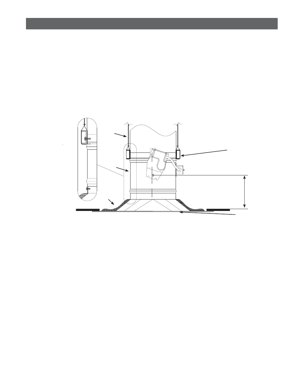
Ducted Recess Mounted Air Inlet Or Outlet Devices
Figure 6
t0QFOJOHJODFJMJOHNFNCSBOFJTNPSFUIBOPOFJODI
MBSHFSUIBOOPNJOBMTJ[FPGDFJMJOHEBNQFS JFJGUIF
ceiling radiation damper is 12 in. diameter [305mm]
(nominal), the ceiling membrane opening is larger
than 13 in. diameter [330mm]).
t.BYJNVNTJ[FPGPQFOJOHJTJOEJBNFUFS TR
in.).
t5IFSNBMCMBOLFUJTSFRVJSFE 4FF1BHF
Paragraph 5).
t$POOFDUJPOPGDFJMJOHSBEJBUJPOEBNQFS BJSEFWJDF
neck, and steel duct drop (See Page 2, Paragraph 4)
may be satisfied as follows:
1.
Ceiling radiation damper may be connected
directly to the air device neck and then the
duct drop connected to the damper (See
Detail B, Figure 6).
.PEFMT$3%NBZCFJOTUBMMFEBTTIPXOJO
Figure 6
.
All hanger wires
must be vertical
(not splayed)!
Steel Duct
Ceiling
Radiation
Damper
Air (Inlet or Outlet) Device
16 ga. x 1 1/2 in.
(1.5mm x 38mm)
Steel Channels
(with 9/16 in.
(14mm)minimum
flanges)
Thermal
Blanket
Detail B
9 3/4 in.
(248mm)
Maximum
Unducted Surface Mounted Air Inlet Or Outlet Devices
t.BYJNVNTJ[FPGQFSNJUUFEPQFOJOHFRVBMTNBYJNVN
TJ[FPGBWBJMBCMFMJTUFEDFJMJOHSBEJBUJPOEBNQFST
t Opening in ceiling membrane may be up to one inch
MBSHFSUIBOUIFOPNJOBMTJ[FPGUIFDFJMJOHSBEJBUJPO
damper (i.e. a 12 in. diameter [305mm] ceiling
radiation damper could have a maximum ceiling
membrane opening of 13 in. [330mm]).
t Connection of ceiling radiation damper and air device
neck (See Page 2, Paragraph 4) may be satisfied in
three ways:
1.
Ceiling radiation damper may be connected
directly to the air device neck and supported
by steel channel (See Detail A, Figure 7).
2.
Ceiling radiation damper may be connected
directly to the air device neck and supported
by hanger straps (See Detail B, Figure 7).
3.
Ceiling radiation damper may be connected
directly to the air device neck and supported
by direct suspension with wires looped
through holes in the damper frame before tying
(See Detail C, Figure 7).
Non-Ferrous Air Devices - Air devices that have non-
ferrous frames.
$FJMJOHNFNCSBOFPQFOJOHTUIBUVUJMJ[FOPOGFSSPVT
devices require one of the following:
1.
A steel extension should extend from the ceiling
radiation damper to the bottom surface of the
ceiling membrane and the opening in the ceiling
membrane (see page 2, paragraph 3) should be
equal to the outside of the steel extension (see
Detail D, Figure 7).
2.
A steel angle should be attached to the bottom
of the ceiling radiation damper and span the
gap from the ceiling radiation damper to the
bottom of the ceiling membrane. The steel angle
should overlap the ceiling membrane (see Detail
E, Figure 7).
.PEFMT$3%NBZCFJOTUBMMFEBTTIPXOJO'JHVSF
Dampers Supported Directly From Structure cont....