Dampers supported from ductwork above, Surface mounted air inlet or outlet devices – Greenheck Ceiling Radiation Dampers (826252) User Manual
Page 25
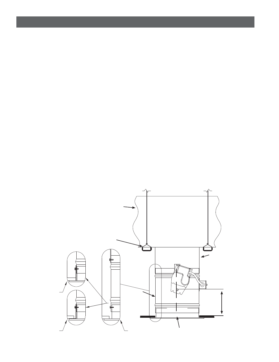
Dampers Supported From Ductwork Above
A Note About Support
When main ducts are supported by 16 ga. x 1½ in.
(1.5mm x 38mm) steel channels (with 9/16 in. [14mm]
minimum flanges) located 1 in. to 3 in. (25.4 mm to
76mm) from and on both sides of a steel duct drop and
these channels are suspended by #12 SWG wire from
structure above, the steel duct drop provides
all required support for ceiling damper and air inlet
or outlet devices. Air device flange must overlap the
ceiling membrane by a minimum of 1 inch (25.4mm).
Follow guidelines in Paragraphs 3 & 4, Page 2 when
preparing opening in the ceiling membrane and
making connections.
Surface Mounted Air Inlet Or Outlet Devices
Figure 3
t.BYJNVNTJ[FPGQFSNJUUFEPQFOJOHFRVBMTNBYJNVN
TJ[FPGBWBJMBCMFMJTUFEDFJMJOHSBEJBUJPOEBNQFST
t0QFOJOHJODFJMJOHNFNCSBOF 4FF1BHF 1BSBHSBQI
NBZCFVQUPPOFJODIMBSHFSUIBOUIFTJ[FPG
the ceiling radiation damper (i.e. a 12 in. diameter
[305mm diameter] ceiling radiation damper could
have a maximum ceiling membrane opening of 13 in.
diameter [330mm]).
t$POOFDUJPOPGDFJMJOHSBEJBUJPOEBNQFS BJSEFWJDF
neck, and steel duct drop (see page 2, paragraph 4)
may be satisfied in as follows:
1.
Ceiling radiation damper may be connected
directly to the air device neck and then the duct
drop connected to the damper (see Detail B,
Figure 3).
Non-Ferrous Air Devices - Air devices that have non-
ferrous frames.
$FJMJOHNFNCSBOFPQFOJOHTUIBUVUJMJ[FOPOGFSSPVT
devices require one of the following:
1.
A steel duct drop from the damper extension
should extend to the bottom surface of the
ceiling membrane and the opening in the ceiling
membrane (see page 2, paragraph 3) should be
equal to the outside of the duct drop (see Detail
C, Figure 3).
2.
A steel angle should be attached to the bottom
of the ceiling radiation damper and span the
gap from the ceiling radiation damper to the
bottom of the ceiling membrane. The steel angle
should overlap the ceiling membrane (see Detail
D, Figure 3).
.PEFMT$3%NBZCFJOTUBMMFEBTTIPXOJO'JHVSF
.
Detail C
Non - Ferrous
Device
Detail D
Non - Ferrous
Device
Detail B
Ferrous
Device
All hanger wires
must be vertical
(not splayed)!
Steel Duct
Ceiling
Radiation
Damper
Steel Duct
Drop
Air
(Inlet or Outlet)
Device
16 ga. x 1 1/2 in. (1.5mm
x 38mm) Steel Channels
(with 9/16 in. (14mm)
minimum flanges)
6 3/4 in.
(171mm)
maximum