Dampers supported directly from structure (cont.), Ducted recess mounted air inlet or outlet devices – Greenheck Ceiling Radiation Dampers (826252) User Manual
Page 8
3
3
/
4
in. Max.
Air (Inlet or Outlet) Device
Ceiling
Radiation
Damper
Steel Duct
Drop
Detail B
Detail A
Thermal Blanket
All hanger wires
must be vertical
(not splayed)!
16 ga. x 1½ in. steel
channels (with 9/16 in.
minimum flanges)
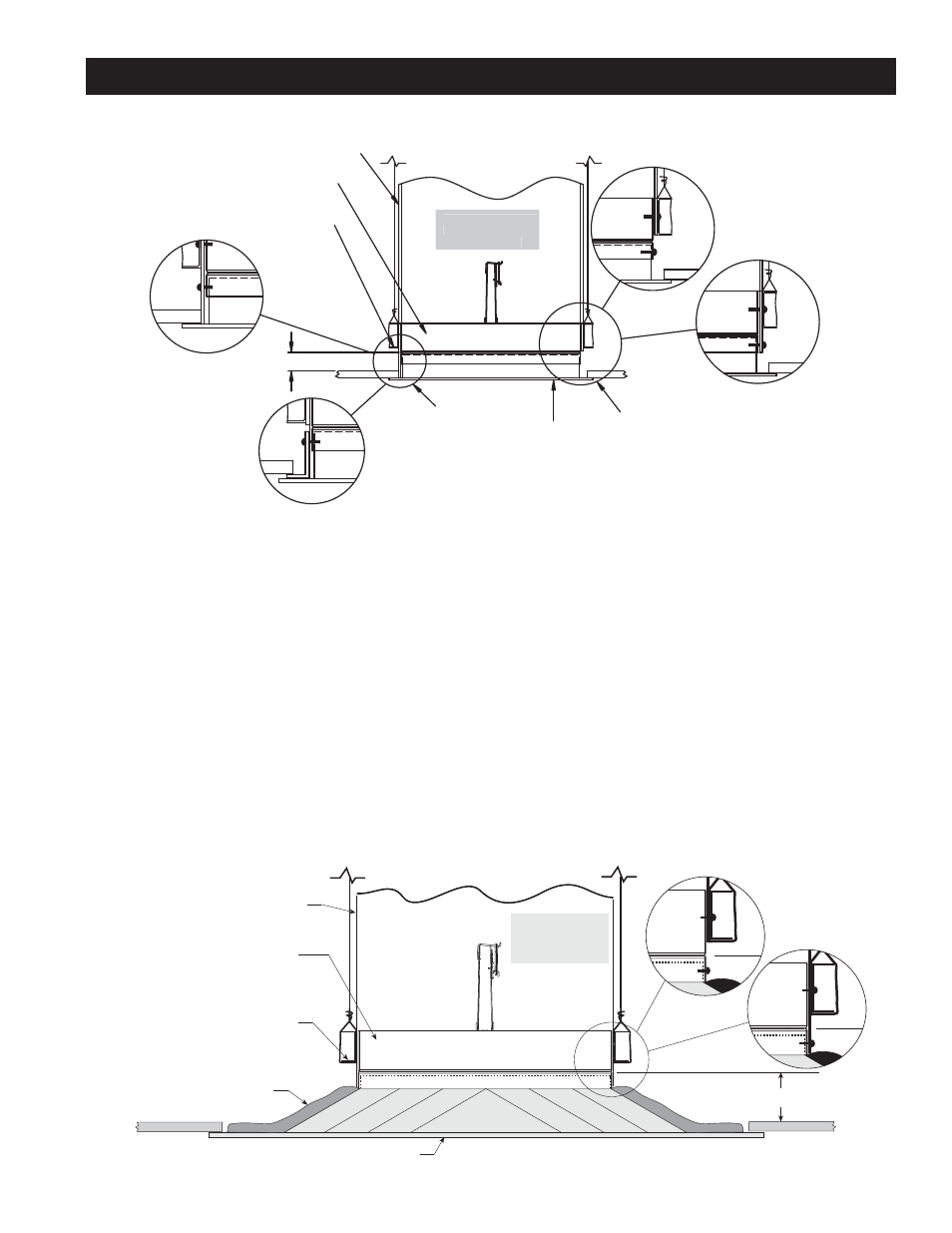
Ducted Recess Mounted Air Inlet Or Outlet Devices
DETAIL
A
DETAIL
B
ALL HANGER WIRES
MUST BE VERTICAL
(NOT SPLAYED)!
Steel Duct
3 3/4 in. Max.
Ceiling Radiation
Damper
16 ga. x 1 1/2 in. Steel
Channels (with 9/16 in.
minimum flanges)
DETAIL
C
DETAIL
D
Air
(Inlet or Outlet)
Device
Metallic
Device
Non-Metallic
Device
ALL HANGER WIRES
MUST BE VERTICAL
(NOT SPLAYED)!
Figure 7
Figure 8
Dampers Supported Directly From Structure (cont.)
t0QFOJOHJODFJMJOHNFNCSBOFJTNPSFUIBOPOFJODI
larger than nominal size of ceiling damper (i.e. if the
ceiling radiation damper is 12 in. x 12 in. (nominal),
the ceiling membrane opening is larger than 13 in. x
13 in.).
t.BYJNVNTJ[FPGPQFOJOHJTJOYJO TR
in.).
t5IFSNBMCMBOLFUJTSFRVJSFE 4FF1BHF 1BSBHSBQI
5).
t$POOFDUJPOPGDFJMJOHSBEJBUJPOEBNQFS BJSEFWJDF
neck, and steel duct drop (See Page 1, Paragraph 4)
may be satisfied in two ways:
1.
Ceiling radiation damper and air device neck
may be connected directly to the duct drop
(See Detail A, Figure 8).
2.
Ceiling radiation damper may be connected
directly to the air device neck and then the
duct drop connected to the damper (See Detail
B, Figure 8).
Models CRD-1, CRD-1LP, CRD-2, and CRD-60 may be
installed as shown in Figure 8 (Model CRD-1 &
CRD-1LP Illustrated)
.
7