Dampers supported directly from structure (cont.), Our commitment – Greenheck Ceiling Radiation Dampers (826252) User Manual
Page 10
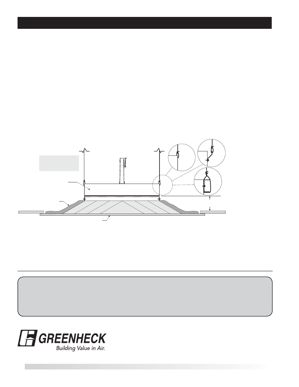
Unducted Recess Mounted Air Inlet Or Outlet Devices
3
3
/
4
in. Max.
Air (Inlet or Outlet) Device
Thermal Blanket
Ceiling
Radiation
Damper
16 ga. x 1½ in. steel
channels (with 9/16 in.
minimum flanges)
Detail C
Detail B
Detail A
All hanger wires
must be vertical
(not splayed)!
Figure 10
Dampers Supported Directly From Structure (cont.)
t0QFOJOHJODFJMJOHNFNCSBOFJTNPSFUIBOPOFJODI
larger than nominal size of ceiling damper (i.e. if the
ceiling radiation damper is 12 in. x 12 in. (nominal),
the ceiling membrane opening is larger than
13 in. x 13 in.).
t.BYJNVNTJ[FPGPQFOJOHJTJOYJO TR
in.).
t5IFSNBMCMBOLFUJTSFRVJSFE 4FF1BHF 1BSBHSBQI
5).
t$POOFDUJPOPGDFJMJOHSBEJBUJPOEBNQFSBOEBJSEFWJDF
neck may be satisfied in three ways:
1.
Ceiling radiation damper may be connected
directly to the air device neck and supported by
steel channel (See Detail A, Figure 10).
2.
Ceiling radiation damper may be connected
directly to the air device neck and supported
by hanger straps (See Detail B, Figure 10).
3.
Ceiling radiation damper may be connected
directly to the air device neck and supported
by direct suspension with wires looped through
holes in the damper frame before tying (See
Detail C, Figure 10).
Models CRD-1, CRD-1LP, CRD-2, and CRD-60 may be
installed as shown in Figure 10 (Model CRD-1 &
CRD-1LP Illustrated).
9
t$3% 3FW 4FQUFNCFS
$PQZSJHIUª(SFFOIFDL'BO$PSQPSBUJPO
As a result of our commitment to continuous improvement, Greenheck reserves the right to change specifications
without notice.
Specific Greenheck product warranties are located on greenheck.com within the product area tabs and in the
Library under Warranties.
®
1IPOF t'BY t&NBJMHGDJOGP!HSFFOIFDLDPNt8FCTJUFXXXHSFFOIFDLDPN
Our Commitment