Dampers supported directly from structure cont – Greenheck Ceiling Radiation Dampers (826252) User Manual
Page 29
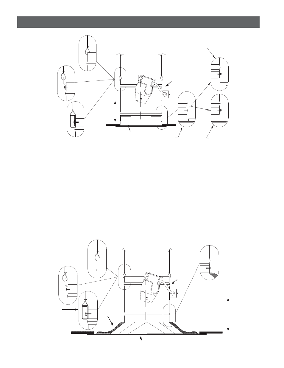
Unducted Recess Mounted Air Inlet Or Outlet Devices
Figure 8
t0QFOJOHJODFJMJOHNFNCSBOFJTNPSFUIBOPOFJODI
MBSHFSUIBOOPNJOBMTJ[FPGDFJMJOHEBNQFS JFJGUIF
ceiling radiation damper is 12 in. diameter [305mm]
(nominal), the ceiling membrane opening is larger than
13 in. [330mm]).
t.BYJNVNTJ[FPGPQFOJOHJTJO TRJO
(610mm [.371 sq. m
])
.
t5IFSNBMCMBOLFUJTSFRVJSFE 4FF1BHF
Paragraph 5).
t$POOFDUJPOPGDFJMJOHSBEJBUJPOEBNQFSBOEBJSEFWJDF
neck may be satisfied in three ways:
1.
Ceiling radiation damper may be connected
directly to the air device neck and supported
by steel channel (See Detail A, Figure 8).
2.
Ceiling radiation damper may be connected
directly to the air device neck and supported by
hanger straps (See Detail B, Figure 8).
3.
Ceiling radiation damper may be connected
directly to the air device neck and supported
by direct suspension with wires looped through
holes in the damper frame before tying (See
Detail C, Figure 8).
.PEFMT$3%NBZCFJOTUBMMFEBTTIPXOJO
Figure 8.
Detail A
Detail C
Detail B
All hanger wires
must be vertical
(not splayed)!
Ceiling
Radiation
Damper
Thermal
Blanket
Air (Inlet or Outlet) Device
16 ga. x 1 1/2 in.
(1.5mm x 38mm) Steel
Channels (with 9/16 in.
(14mm) minimum flanges)
9 3/4 in.
(248mm)
Maximum
Detail D
Non - Ferrous
Device
Detail E
Non - Ferrous
Device
Ferrous
Device
Detail A
Detail B
Detail C
Figure 7
All hanger wires
must be vertical
(not splayed)!
Ceiling
Radiation
Damper
Air
(Inlet or Outlet)
Device
6 3/4 in.
(171mm)
maximum
Dampers Supported Directly From Structure cont....