Field installation of steel plenums cont – Greenheck Ceiling Radiation Dampers (826252) User Manual
Page 20
1.
Fiberglass ductboard shall be a minmum of 1 inch
(25mm) thick UL181 Listed and have a minmum
R-value 4.3 .
2.
The inside width x length dimensions on the duct
board plenum shall be sized no greater than 1/8 in.
(3mm) larger than the damper frame. The maximum
plenum height shall be 15 in. (381mm) as illustrated
below. The plenum should be sized to provide a
snug fit over the damper frame.
3.
Edge and corner preparation shall be accordance
with details shown (Figures 9 and 10). Plenum
top shall be fabricated and attached using similar
method, S-AF and SF-AF (Figures 9 and 10).
4.
Corner sealing tape shall be UL 181 Listed and
minimum of 2 in. ( 51mm) wide.
AF - Square Cut
with Flap
AF - Square Cut
S - Female Shiplap
SF - Female Shiplap with
End Flap
VC - V-groove
Corner Fold
SC - Shiplap
Corner Fold
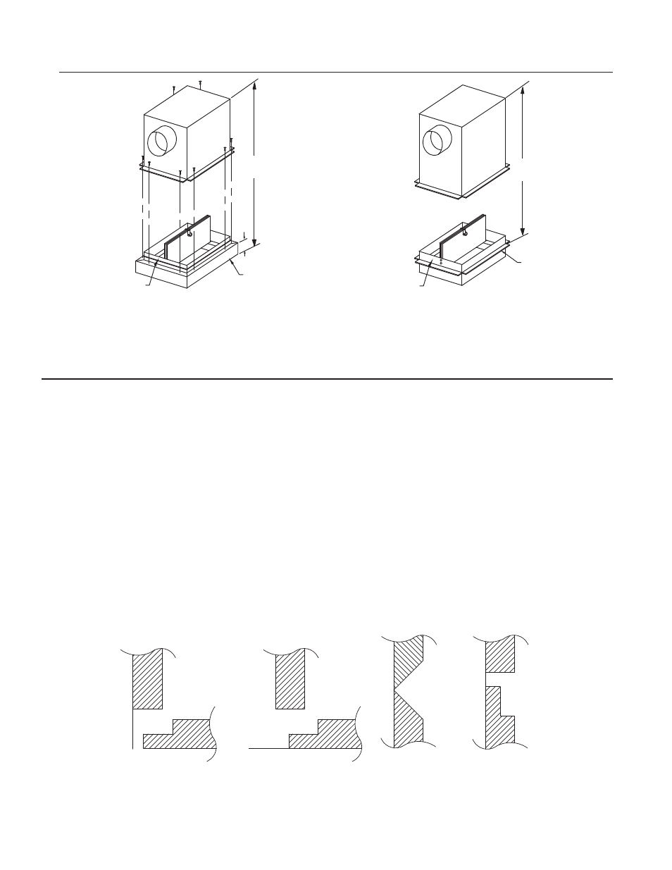
Fabrication of Fiberglass Ductboard Plenum for CRD-1WT
Figure 9
Damper and Steel Plenum
Assembly
CRD-1WT Grille Mount
Damper and Steel Plenum
Assembly
CRD-1WT Duct Mount
Plaster
Flange
Plaster
Flange
Damper
Frame
Damper
Frame
3.5 in.
14 in.
maximum
14 in.
maximum
Figure 8
Field Installation of Steel Plenums cont........
5.
The plenum duct collars shall be minimum of 30
ga. (.39mm) galvanized steel. The total area of the
plenum box duct collars shall not exceed 78.5 sq. in.
(1994 sq. mm) with a maximum of two duct collars
per plenum. Duct collars shall be securely fastened
to the plenum duct board. Any segment of the duct
collar that protrudes inside the plenum must not
interfere with the damper blade operation.
6.
Plenum shall be attached to ceiling damper sub-
frame using UL 181 Listed tape (Figure 11).
7.
Refer to Figure 4- 7 for ceiling damper installation.
The CRD-1WT ceiling radiation damper is classified
for use in specific wood truss ceiling assemblies. See
UL Fire Resistance Directory for floor/ceiling design
number M508 and roof/ceiling design number P554.