Gasboy 580 Series User Manual
Page 20
Wiring
Conduit
Page 16
MDE-4766 Series 580 Installation/Operation/Parts Manual · April 2009
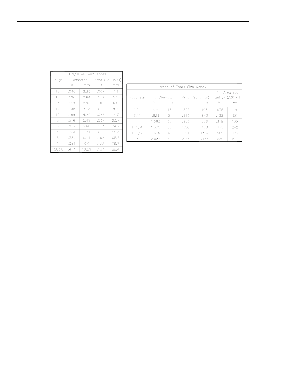
Use the charts below as a guideline to determine the proper conduit sizes. When planning the
orientation of the wiring runs, follow the applicable Gasboy wiring diagram and consider the
layout of the components at the site. Long runs or a large number of bends may require you to
increase conduit size over what is listed, to aid in pulling wires through the conduit.
To determine conduit size needed, use the THHN/THWN Wire Areas table (left) to find the
area for each wire gauge. Add up all wire areas. Use the Areas of Trade Size Conduit Table
(right) to select the smallest number in the 25% fill area (based on NEC 501-1) that comes
closest without exceeding the total wire area.
Notes:1) Pulling of spare wires is highly recommended should wire damage occur at a later
date.
2) All wiring and conduit runs must conform with all building/fire codes, all Federal,
State, and Local codes, National Electrical Code, (NFPA 70), NFPA 30, and
Automotive and Marine Service Station Code (NFPA 30A) codes and regulations.
3) Some motors contain a brown wire (Switch Detect) which is capped at the factory.
When used, it connects to a solenoid valve or fuel management system. Do not connect
this wire without first checking the ON voltage of this line to ascertain compatibility
with the equipment being connected.
4) All wiring must be installed according to the requirements outlined in this section.