Hardware connections, Determining the correct positions for sw1 and sw2 – Gasboy CFN Series Gilbarco Pump PC Interface User Manual
Page 10
Configuration
Hardware Connections
Page 6 MDE-4634 CFN Series Gilbarco® Pump PC Interface for Site Controller III with Windows NT® · November 2007
Hardware Connections
Use a standard PC DB9 to DB25 cable (Gasboy part number C06253) to connect the selected
PC COM port to the DB25 connector of the IC-485S (Gasboy part number C08087). The
following illustration provides an overview of the connections.
C05981
Adapter
485
Input
DB9
IC-485S
Power
Supply
RJ11
Conn.
C05999
Cable
TB
CFN
3
C06253
DB9/DB25
C08087
IC-485S
Gilbarco
Distribution Box
set up for
RS-422
operation
This section connected according to
Gilbarco's wiring instructions by a qualified
Gilbarco installer.
CURRENT LOOP
Pump
Pump
Pump
COM
Port
SW1 and SW2 of the IC-485S Converter should be set to DCE and T-on R-on. Connect the
power supply to the power jack of the converter and plug the standard outlet cable into an
available outlet, preferably on a backup power supply or power conditioner.
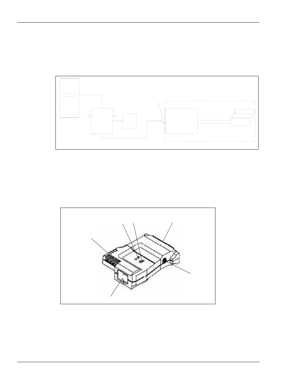
Determining the Correct Positions for SW1 and SW2
The following figure provides the external view of IC-485.
Power Jack
RS-232 DB-25 Female
Connector
SW2
SW1
Terminal Block
RJ-11(IC-485S) GND TAB(IC-485SI)
Two side switches are used to configure its operation mode, contention control, and
assignment of the RS-232.
Note: For the correct location of SW1 and SW2, see the figure above.